Advertisement
Available languages
Available languages
Quick Links
Anwenderhinweise
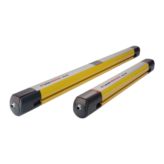
Mehrstrahl-Sicherheits-Lichtschranken MLD
User notes
MLD multiple light beam safety devices
Instrucciones de usuario
Dispositivos de seguridad multihaz MLD
Conseils d'utilisation
Barrages immatériels multifaisceaux de sécurité MLD
Istruzioni per l'uso
Barriere fotoelettriche multiraggio di sicurezza MLD
Instruções do usuário
Barreiras de luz de segurança de múltiplos feixes MLD
사용자 지침
다중빔 안전 광전 감지기 MLD
用户提示
多光束安全光栅 MLD
Kullanıcı bilgileri
Çok ışınlı emniyet bariyerleri MLD
Leuze electronic GmbH + Co. KG
In der Braike 1 73277 Owen Tel.: +49 7021 573-0
MLD
info@leuze.com
•
www.leuze.com
Advertisement

Related Manuals for Leuze MLD510-R3M/A


Summary of Contents for Leuze MLD510-R3M/A
- Page 1 Barreiras de luz de segurança de múltiplos feixes MLD 사용자 지침 다중빔 안전 광전 감지기 MLD 用户提示 多光束安全光栅 MLD Kullanıcı bilgileri Çok ışınlı emniyet bariyerleri MLD Leuze electronic GmbH + Co. KG In der Braike 1 73277 Owen Tel.: +49 7021 573-0 info@leuze.com • www.leuze.com...
- Page 2 Gültigkeit Diese Anwenderhinweise gelten für die Mehrstrahl-Sicherheits-Lichtschranken MLD. Sicherheit Für Montage, Betrieb und Prüfungen müssen dieses Dokument, die Originalbe- triebsanleitung sowie alle zutreffenden nationalen und internationalen Normen, Vorschriften, Regeln und Richtlinien beachtet werden. Relevante und mitgelieferte Dokumente müssen beachtet, ausgedruckt und an das betroffene Personal wei- tergeben werden.
- Page 3 Sicherheits-Sensors enthält die einschlägige Betriebsanleitung. Sie finden die Originalbetriebsanleitung und die EU-Konformitätserklärung, indem Sie auf unse- rer Website www.leuze.com die Artikelnummer des Sicherheits-Sensors in das Suchfeld eingeben. Die Artikelnummer kann auf dem Typenschild des Sensors unter dem Eintrag „Part. No.“ abgelesen werden.
- Page 4 Betriebsanzeigen am Receiver 7-Segment-Anzeige LED2 Strahlaustritt LED1 Am Receiver befinden sich unten je nach Typ eine oder zwei Leuchtdioden (LED1, ggf. LED2). LED1 Bedeutung Grün Dauerlicht OSSD* ein Rot Dauerlicht OSSD* aus Rot langsam blinkend Anwenderfehler, externer Fehler (ca. 1 Hz) Rot schnell blinkend Gerätefehler, interner Fehler (ca.
- Page 5 Betriebsanzeigen am Transceiver Am Transceiver befinden sich je nach Typ eine oder zwei Leuchtdioden (LED1, ggf. LED2) im unteren Bereich (vgl. Receiver) sowie je nach Typ eine 7-Segment- Anzeige (vgl. Receiver) und an den Lichtachsen im oberen Bereich je eine grüne LED (vgl.
-
Page 6: Montage Und Inbetriebnahme
Montage und Inbetriebnahme Befestigen Ä Geräte mit der gewünschten Befestigungsart befestigen (Halter separat be- stellen), beide Typenschilder entweder oben oder unten. Grobausrichtung und Anbringen der Laserwarn- und Laserhinweisschilder Ä Geräte weitestgehend parallel und auf gleicher Höhe, Frontscheiben zueinan- der gerichtet ausrichten. Bei Geräten mit integrierter Laserausrichthilfe Laser- warn- und Laserhinweisschilder gut sichtbar anbringen. - Page 7 Prüfen Grün Grün/gelb+rot/rot Ä Status LEDs prüfen: Dauerleuchten Falls nicht wie angegeben: Fehlerbehebung in Betriebsanleitung MLD Kapitel 11 „Fehler beheben“. Ausrichten Ä Schrauben der Halterungen bzw. der Gerätesäulen lösen. Ä Wenn vorhanden, integrierte Laserausrichthilfe mit Magnet Key am Transmit- ter aktivieren. Ä...
- Page 8 EU Declaration of Conformity by entering the part number of the safety sensor in the search field on our website www.leuze.com. The part number can be read on the name plate of the sensor under the "Part No."...
-
Page 9: Display Elements
Display elements Operating indicators on the transmitter Beam exit There is a green LED at each light axis of the transmitter serving as a function in- dicator. Description Green Transmitted beam active Error (transmitted beam inactive, error or no voltage supply) Operating indicators on the receiver 7‑segment display LED2... - Page 10 LED2 (MLDx20/x30/x35 only) Meaning – The light path is free Yellow, continuous light – Start/restart interlock locked – Waiting for acknowledgment sig- Information on the flashing behavior with MLD/AS-i devices can be found in chap- ter 11.2 of the MLD operating instructions. Meaning of the 7-segment display (MLDx20/x30/x35 only) Display Meaning...
-
Page 11: Mounting And Commissioning
Colored indicator light (if present) Indicator Indicator Meaning Green OSSD on OSSD off – The light path is free Yellow/red, alternating – Start/restart interlock locked – Waiting for acknowledgment sig- – OSSDs off Red, flashing slowly OSSD off, user error (approx. 1 Hz) Red, flashing fast OSSD off, device error... - Page 12 Connection Connection of machine interface Local socket Ä Connect the device and switch on the voltage supply. Device/Operating mode M12 connector Connection Transmitter 5-pin connector Receiver/Transceiver 5-pin connector or 8-pin Connection to the ma- MLDx10/20 connector chine interface (1) – 8-pin connector –...
- Page 13 Alignment Ä Loosen the screws on the mounting brackets or device columns. Ä If present, activate the integrated laser alignment aid with magnet key on the transmitter. Ä Align the device or device column with device by tipping, tilting and turning. Optimum alignment: Middle of the twist angle at which the LED(s) are only just lit red and yellow or green.
- Page 14 Validez Estas instrucciones de usuario tienen validez para los dispositivos de seguridad multihaz MLD. Seguridad Para el montaje, el funcionamiento y las comprobaciones deben observarse este documento, las instrucciones originales de uso y todas las normas, prescripcio- nes, reglas y directivas nacionales e internacionales pertinentes. Igualmente de- berá...
-
Page 15: Elementos De Indicación
UE introdu- ciendo el código del sensor de seguridad en el campo de búsqueda en nuestro si- tio web www.leuze.com. El código se puede encontrar en la placa de característi- cas del sensor bajo «Part. No.». - Page 16 Indicadores de funcionamiento en el receptor Display de 7 segmentos LED2 Salida del haz LED1 Según el modelo, en el receptor hay uno o dos diodos luminosos (LED1 y, dado el caso, LED2). LED1 Significado Verde, luz continua OSSD* activada Rojo, luz continua OSSD* desactivada Rojo con parpadeo lento...
- Page 17 Significado del display de 7 segmentos (solo MLDx20/x30/x35) Indicación Significado 1 … 6 Modo de trabajo elegido durante el funcionamiento normal F … Error del equipo, error interno E … Error de usuario, error externo U … Usage Event, error de funcionamiento (p. ej. error de muting) 8 o .
- Page 18 Montaje y puesta en marcha Fijación Ä Fijar los equipos con el tipo de fijación deseado (pedir soporte por separado), ambas placas de características o bien arriba o bien abajo. Alineación estimada y colocación de las placas de aviso y de advertencia de láser Ä...
- Page 19 Comprobar Verde Verde/amarillo+rojo/rojo Ä Comprobar LED de estado: luces continuas Si no es como se especifica: consultar la eliminación de errores en las instruccio- nes de uso MLD, capítulo 11 «Eliminación de errores». Alineación Ä Suelte los tornillos de los soportes o las columnas de montaje. Ä...
- Page 20 Validité Ces conseils d’utilisation s’appliquent aux barrages immatériels multifaisceaux de sécurité MLD. Sécurité Pour le montage, l'exploitation et les contrôles, il convient de prendre en compte ce document, le manuel d'utilisation d'origine ainsi que toutes les normes, pres- criptions, règles et directives nationales et internationales qui s'appliquent. Les do- cuments pertinents et livrés doivent être observés, imprimés et remis au person- nel concerné.
-
Page 21: Éléments D'affichage
UE en entrant le numéro d'article du capteur de sécurité dans le champ de recherche sur notre site internet à l'adresse www.leuze.com. Le nu- méro d'article est indiqué sur la plaque signalétique du capteur dans le champ « Part No. ». - Page 22 Selon le type, le récepteur dispose d’une ou de deux LED (LED1 et le cas échéant LED2), en bas. LED1 Signification Verte, lumière permanente OSSD* active Rouge, lumière permanente OSSD* inactive Rouge clignotant lentement Erreur de l’utilisateur, erreur externe (Env. 1 Hz) Rouge clignotant rapidement Erreur de l'appareil, erreur interne (Env.
- Page 23 Témoin lumineux de couleur (le cas échéant) Témoin lumineux Témoin lumineux Signification Vert OSSD active Rouge OSSD inactive – Faisceau établi Jaune/rouge en alternance – Blocage démarrage/redémarrage verrouillé – Attente d'un signal d’acquittement – OSSD inactives Rouge, clignotant lentement OSSD inactive, erreur de l’utilisateur (env. 1 Hz) Rouge, clignotant rapidement OSSD inactives, erreur de l'appareil...
- Page 24 Raccordement Raccordement de l'interface machine Prise femelle locale Ä Raccorder l’appareil et allumer l’alimentation en tension. Appareil/mode de fonc- Connecteur M12 Connexion tionnement Émetteur Prise mâle à 5 pôles Récepteur/transceiver Prise mâle à 5 ou 8 pôles Connexion à l’interface MLDx10/20 machine (1) –...
- Page 25 Alignement Ä Desserrer les vis des supports ou des montants. Ä Le cas échéant, activer l’aide à l'alignement laser sur l’émetteur au moyen de la MagnetKey. Ä Orienter l’appareil ou le montant avec appareil en les basculant, les inclinant ou les tournant. Orientation optimale : Au milieu de l’angle auquel la ou les LED brillent encore tout juste en rouge et jaune ou en vert, selon le cas.
- Page 26 Validità Queste istruzioni per l'uso valgono per le barriere fotoelettriche multiraggio di sicu- rezza MLD. Sicurezza Per il montaggio, il funzionamento e i controlli è necessario rispettare questo do- cumento, il manuale di istruzioni originale nonché tutte le norme, disposizioni, re- gole e direttive nazionali ed internazionali pertinenti.
-
Page 27: Elementi Di Visualizzazione
UE inserendo sul nostro sito web www.leuze.com il co- dice articolo del sensore di sicurezza nel campo di ricerca. Il codice articolo si tro- va sulla targhetta identificativa del sensore alla voce «Part. No.». Il sensore di sicurezza soddisfa i requisiti essenziali e le altre disposizioni perti- nenti della Direttiva Macchine 2006/42/CE. - Page 28 Sul ricevitore si trovano, a seconda del tipo, uno o due diodi luminosi (LED1, e- ventualm. LED2). LED1 Significato Verde, costantemente acceso OSSD* accesa Rosso, costantemente acceso OSSD* spenta Rosso lampeggiante lentamente Errore utente, errore esterno (circa 1 Hz) Rosso lampeggiante velocemente Errore del dispositivo, errore interno (circa 10 Hz) Verde lampeggiante lentamente...
- Page 29 Indicatore luminoso colorato (se presente) Lampada Lampada Significato Verde OSSD accesa Rosso OSSD spenta – Percorso ottico libero Giallo/rosso in alternanza – Blocco di avvio/riavvio bloccato – Attesa del segnale di conferma – OSSD spenta Rosso, lampeggio lento OSSD spenta, errore utente (circa 1 Hz) Rosso, lampeggio rapido OSSD spenta, errore dispositivo...
- Page 30 Collegamento Collegamento per l'interfaccia macchina Presa locale Ä Collegare il dispositivo e attivare l'alimentazione di tensione. Dispositivo/Modo operati- Connettore circolare M12 Collegamento Trasmettitore Connettore maschio a 5 poli Ricevitore/transceiver ML- Connettore maschio a 5 Collegamento con l'inter- Dx10/20 poli o connettore maschio faccia macchina (1) a 8 poli –...
- Page 31 Allineamento Ä Svitare le viti dei supporti ossia delle colonne di fissaggio. Ä Laddove presente attivare il dispositivo laser di allineamento integrato con MagnetKey sul trasmettitore. Ä Allineare il dispositivo o la colonna di fissaggio basculandoli, inclinandoli e ruotandoli. Allineamento ottimale: Centro dell'angolo di rotazione, dove il/i LED sono ancora accesi in rosso, giallo e/ o verde.
- Page 32 Validade Estas instruções do usuário são válidas para as barreira de luz de segurança de múltiplos feixes MLD. Segurança Para fins de montagem, operação e teste, este documento, o manual de instru- ções original, assim como todas as normas nacionais e internacionais, prescri- ções, regras e diretrizes, devem ser seguidos.
- Page 33 CE de Conformidade, vi- site o nosso website www.leuze.com e introduza o número de artigo do sensor de segurança no campo de pesquisa. O número de artigo pode ser consultado na etiqueta de identificação do sensor, na entrada «Part.No.».
- Page 34 Um ou dois díodos luminosos (LED1 e, se for o caso, LED2) se encontram na parte inferior do receptor, dependendo do tipo de receptor. LED1 Significado Luz fixa verde OSSD* ligada Vermelho, luz contínua OSSD* desligada Luz vermelha piscando lentamente Erro do usuário, erro externo (Cerca de 1 Hz) Luz vermelha piscando rapidamente...
- Page 35 Indicador luminoso colorido (se existente) Indicador luminoso Indicador luminoso Significado Verde OSSD ligada Vermelho OSSD desligada – Caminho ótico livre Amarelo/vermelho, intermitente – Intertravamento de inicialização/ rearme bloqueado – Aguardando sinal de confirmação – OSSD desligadas Vermelho piscando lentamente OSSD desligada, erro de usuário (aprox. 1 Hz) Vermelho piscando rapidamente OSSD desligada, erro de dispositivo...
- Page 36 Conexão Conexão da interface de máquina Conector fêmea local Ä Conectar o dispositivo e ligar a alimentação de tensão. Dispositivo/modo de ope- Conector M12 Conexão ração Transmissor Conector macho de 5 pó- Receptor/transceiver ML- Conector macho de 5 po- Conexão com a interface Dx10/20 los ou conector macho de da máquina (1)
- Page 37 Alinhamento Ä Solte os parafusos dos suportes e/ou das colunas de dispositivos. Ä Se existente, ativar o laser de alinhamento integrado com o MagnetKey no transmissor. Ä Alinhar o dispositivo e/ou a coluna de dispositivos com o dispositivo rebaten- do, inclinando e girando. Alinhamento ideal: Ao centro do ângulo de rotação, no último ponto no qual o(s) LED(s) ainda fica(m) aceso(s) em vermelho e amarelo ou verde.
- Page 38 – 장치 앞유리에 김서림 및 얼음이 생길 수 있는 환경. 안전센서의 안전한 실행과 점검, 운용에 관한 상세 정보는 해당 사용 설명서를 참조 하십시오. www.leuze.com에서 검색란에 안전센서의 품목 번호를 입력하여 사용 설명서 원본 및 EU 준수선언서를 찾을 수 있습니다. 품목 번호는 센서 명찰의...
- Page 39 표시 장치 송신기 작동 표시 빔 방향 송신기에는 각 라이트 축마다 기능 표시를 위한 녹색 LED 한 개가 있습니다. 설명 녹색 송신 빔 활성화 꺼짐 오류(송신 빔 비활성화, 오류가 있거나 전원이 공급되지 않음) 수신기의 조작 표시창 7 세그먼트 디스플레이 LED2 빔...
- Page 40 LED2(MLDx20/x30/x35만 해당) 의미 – 광센서 경로 비었음 황색 연속 점등 – 재시동/시동 인터로크 잠김 – 확인 신호 대기 MLD/AS-i 장치의 깜빡임 동작에 대한 정보는 MLD 조작 지침의 11.2장에서 확인할 수 있습니다. 7 세그먼트 디스플레이의 의미(MLDx20/x30/x35만 해당) 디스플레 의미 이 1 ~ 6 정상...
- Page 41 표시 램프 의미 녹색 천천히 깜빡임 OSSD 켜짐, 약한 신호 (약 1Hz) 흰색 뮤팅(MLDx30 및 MLDx35의 경우) 흰색 깜빡임/흰색/적색 깜빡임 뮤팅 오류(MLDx30 및 MLDx35의 경우) 설치 및 시운전 고정 Ä 장치를 원하는 마운팅 브라켓 유형으로 고정하십시오(홀더는 별도로 주문). 레이저 경고판 및 레이저 표지판의 대략적인 정렬 및 부착 Ä...
- Page 42 점검 녹색 녹색/황색+적색/적색 Ä LED 상태 점검: 지속 점등 명시된 상황과 다른 경우 MLD 조작 지침 11장 "오류 해결"을 참조하여 오류를 해결 하십시오. 설정 Ä 고정 장치 또는 장치 포스트의 나사를 푸십시오. Ä 레이저 정렬 보조 장치가 통합되어 있는 경우 마그넷 키를 이용하여 송신기에 서...
- Page 43 仅由专业人员安装安全传感器。 Ä 保持必要的安全距离。另请注意与反射面的最小距离。 Ä 防止来自临近系统的光学串扰。 Ä 安全排除从后面进入、从下面爬过和从上面翻越防护装置等情况,根据 EN ISO 13855标准通过附加值CRO将上/下和周围接近等可能纳入安全距离考 虑范围。 Ä 采取合适措施,防止使用安全传感器通过攀爬等手段进入危险区域。 Ä 定期清洁设备。 Ä 激活用于出入口保护的启动/重启联锁装置,因为仅识别进入危险区域,而不识 别是否有人停留。 Ä 用于解锁启动/重启联锁装置的确认单元不得从危险区域能够接触,并且必须保 证能够观察整个危险区域。 Ä 安装后检查安全传感器的功能。 Ä 必须防止机器在没有合适防护装置的情况下自动运行。在维护工作期间,例如 改造、调整、测试时,系统必须安全关闭或采取其他降低风险的措施。 MLD 系列的多光束安全光栅规定不得用于以下环境条件中: – 在可导致冷凝的高空气湿度环境中。 – 产品可直接接触到水的环境中。 – 可导致设备前置镜上形成水汽和结冰的环境中。 相关使用说明书中包含有关安全传感器的安全实施、检查和运行的详细信息。您可 以通过在我们网站 www.leuze.com 上的搜索栏中输入安全传感器的产品编号来查 找原版使用说明书和欧盟符合性声明。订货号参见传感器铭牌上的“部件号”条目。 安全传感器满足机械指令 2006/42/EG 的基本要求和其他相关规定。...
- Page 44 显示元件 发射器上的运行显示 光线出口 在发射器的每一个光轴上有一个绿色LED功能显示器。 说明 绿色 发射束激活 关 错误(发射光束未激活、错误或无电源) 接收器上的运行显示 7段显示器 LED2 光线出口 LED1 根据类型,接收器底部有一个或两个发光二极管(LED1,必要时存在 LED2)。 LED1 说明 绿色,连续常亮 OSSD*开 亮红灯 OSSD*关 红色,低速闪烁 用户错误,外部错误 (约 1 Hz) 红色,快速闪烁 设备故障,内部故障 (约 10 Hz) 绿色,低速闪烁 OSSD*开, 弱信号 (约 1 Hz) * 输出开关元件(输出开关信号设备)可靠地显示安全相关事件并将其传递给控制 器...
- Page 45 LED2(仅 MLDx20/x30/x35) 说明 – 光路畅通 黄色,常亮 – 重启/启动联锁装置已锁定 – 等待确认信号 有关 MLD/AS-i 设备闪烁特征的信息,参见 MLD 使用说明书章节 11.2。 7 段显示器的含义(仅 MLDx20/x30/x35) 显示 说明 1 … 6 所选运行模式处于正常运行状态 F … 设备故障,内部故障 E … 用户错误,外部错误 U … 使用事件,运行错误(例如屏蔽错误) 8 或 启动错误(见第 11 章) 显示消息的详细列表,参见 MLD 使用说明书章节 11.3。 收发器上的运行显示 根据型号不同,收发器在下部区域有一个或两个发光二极管(LED1,必要时存在 LED2)(见接收器),同时根据型号不同,有一个 7 段显示器(见接收器)并在 上部区域中的光轴上有一个绿色...
- Page 46 指示灯 说明 闪烁白色 / 闪烁白色/红色 屏蔽错误(对于 MLDx30 和 MLDx35) 安装和调试 固定 Ä 使用所需的固定方式固定设备(支架需单独订购),两个铭牌位于上方或下 方。 粗略校准并安装激光警告标签和信息提示标签 Ä 将设备尽可能平行且在同一高度对齐,挡风玻璃彼此相对。对于集成激光校准 仪的设备,请安装激光警告标签和信息提示标签,使其清晰可见。 连接 机器接口连接 本地插口 Ä 连接设备并开启电源。 设备/运行模式 M12接头 连接 发射器 5针接头 接收器/收发器 MLDx10/20 5 针插头或 8 针插头 连接机器接口(1) – 8引脚插头 – 连接机器接口(1) 接收器/收发器 MLDx30/35 –...
- Page 47 检查 绿色 绿色/黄色+红色/红色 Ä 检查状态 LED:常亮 如果不符合规定:按照 MLD 使用说明书第 11 章“故障排除”进行故障排除。 对准 Ä 松开支架或设备柱的螺钉。 Ä 如有,请使用发射器上的磁铁钥匙激活集成的激光校准仪。 Ä 通过翻转、倾斜和旋转来将设备或设备柱与设备对准。 最佳校准: 旋转角度的中间,在该位置时 LED 仍然发出红色和黄色或绿色光。 Ä 重新拧紧校准螺钉。...
- Page 48 Emniyet sensörünün güvenli bir şekilde faaliyete alınması, kontrol edilmesi ve işle- tilmesine yönelik ayrıntılı bilgiler ilgili çalışma talimatlarında bulunmaktadır. www.leuze.com internet sitemizdeki arama alanına emniyet sensörünün numara- sını girerek orijinal çalışma talimatlarını ve AB Uygunluk Beyanını bulabilirsiniz. Ü- rün numarası «Part. No.» kaydı altında sensörün etiketinden okunabilir.
- Page 49 Gösterge elemanları Aktarıcıdaki çalışma göstergeleri Işın çıkışı Aktarıcıda, her optik eksende işlev göstergesi için yeşil bir LED yer alır. Tanım Yeşil Verici ışını aktif Kapalı Hata (verici ışını aktif değildir, hata veya gerilim beslemesi yok) Alıcıdaki çalışma göstergeleri 7 segmentli ekran LED2 Işın çıkışı...
- Page 50 LED2 (sadece MLDx20/x30/x35) Anlam – Işık yolu boş Sarı, sürekli ışık – Start/restart kilidi kilitli – Onaylama sinyalini bekleyin MLD/AS-i cihazlarındaki sinyal davranışı ile ilgili bilgiler, MLD kullanma kılavuzun- da Bölüm 11.2’de yer alır. 7 segmentli ekranın anlamı (sadece MLDx20/x30/x35) Ekran Anlam 1 … 6...
- Page 51 Gösterge Anlam Beyaz Susturma (MLDx30 ve MLDx35’de) Beyaz yanıp sönme / beyaz/kırmızı ya- Susturma hatası (MLDx30 ve ML- nıp sönme Dx35’de) Montaj ve devreye alma Sabitleme Ä Cihazları, istenilen montajlama türüne göre sabitleyin (tutucuyu ayrıca sipariş edin), her iki isim levhası üstte veya altta. Lazer ikaz ve uyarı...
- Page 52 Cihaz/işletim türü M12 yuvarlak konnektör Bağlantı MLDx20/30/35 cihaz var- 8 kutuplu konnektör Makine arayüzündeki (1) yantlarının çalışma modu bağlantıda pim tahsisi ü- seçimi zerinden Pim tahsisi ve konfigürasyon ile ilgili diğer bilgileri MLD kullanma kılavuzunda bu- lunur. Kontrol Yeşil Yeşil/sarı+kırmızı/kırmızı Ä...
Need help?
Do you have a question about the MLD510-R3M/A and is the answer not in the manual?
Questions and answers