Table of Contents
Advertisement
Quick Links
SERVICE MANUAL
Ver. 1.1 2011.08
AUDIO POWER SPECIFICATIONS
POWER OUTPUT AND TOTAL HARMONIC DISTORTION
220 watts per channel minimum continuous average power into 4 ohms,
both channels driven from 20 Hz to 20 kHz with no more than 1% total
harmonic distortion per Car Audio Ad Hoc Committee standards.
Other Specifi cations
Circuit system
OTL (output transformerless) circuit
Pulse power supply
Inputs
RCA pin jacks
High level input connector
Outputs
Speaker terminals
Through out pin jacks
Suitable speaker impedance
2 8 (stereo)
4 8 (when used as a bridging amplifi er)
440 W 2 (at 4 )
Maximum outputs
650 W 2 (at 2 )
1,400 W (BTL) (at 4 )
Rated output (supply voltage at 14.4 V, 20 Hz 20 kHz, 1% THD + N)
220 W 2 (at 4 )
270 W 2 (at 2 )
540 W (BTL) (at 4 )
Frequency response 10 Hz 50 kHz (
Input level adjustment range
0.3 6.0 V (RCA pin jacks)
1.2 12.0 V (High level input)
50 Hz 300 Hz, 12 dB/oct
Low-pass fi lter
6 Hz 70 Hz, 12 dB/oct
Subsonic fi lter
0 10 dB (40 Hz)
Low boost
Power requirements 12 V DC car battery (negative ground)
Power supply voltage
10.5 16 V
at rated output: 50 A (at 4 )
Current drain
Remote input: 1 mA
9-889-724-02
Sony Corporation
2011H33-1
©
2011.08
Published by Sony Techno Create Corporation
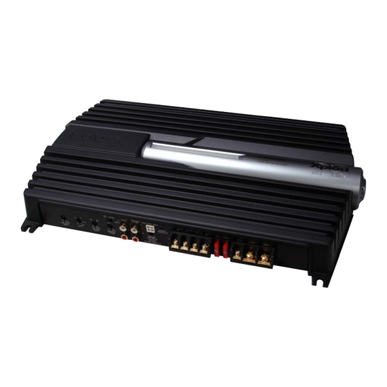
XM-GTR2202
SPECIFICATIONS
+0
dB)
–3
Approx. 424 55 280 mm
Dimensions
2
11
(16
3/4
1/4
projecting parts and controls
Mass
Approx. 3.6 kg (7 lb 15 oz) not incl. accessories
Supplied accessories
Mounting screws (4)
High level input cord (1)
Protection cap (1)
Design and specifi cations are subject to change without notice.
Dimensions / Dimensions / Dimensiones
Unit: mm (in)
Unité : mm (po)
Unidad: mm
424 (16
354 (14)
354 (14)
STEREO POWER AMPLIFIER
US Model
Canadian Model
AEP Model
UK Model
E Model
in) (w/h/d) not incl.
1/8
55
/
)
(2
1
/
)
3
4
4
ø 6 (
1
/
)
4
Advertisement
Table of Contents

Related Manuals for Sony XM-GTR2202


Summary of Contents for Sony XM-GTR2202
- Page 1 Power supply voltage 10.5 16 V at rated output: 50 A (at 4 ) Current drain Remote input: 1 mA 354 (14) ø 6 ( STEREO POWER AMPLIFIER 9-889-724-02 Sony Corporation 2011H33-1 © 2011.08 Published by Sony Techno Create Corporation...
-
Page 2: Table Of Contents
LES DIAGRAMMES SCHÉMATIQUES ET LA LISTE DES PIÈCES SONT CRITIQUES POUR LA SÉCURITÉ DE FONC- TIONNEMENT. NE REMPLACER CES COMPOSANTS QUE PAR DES PIÈCES SONY DONT LES NUMÉROS SONT DON- NÉS DANS CE MANUEL OU DANS LES SUPPLÉMENTS PUBLIÉS PAR SONY. -
Page 3: General
XM-GTR2202 SECTION 1 This section is extracted GENERAL from instruction manual. Connections/Connexions/Conexiones Make the terminal connections as illustrated below. Procédez aux connexions des bornes comme illustré ci-dessous. Realice las conexiones de terminal como se ilustra a continuación. Installation Before Installation... - Page 4 XM-GTR2202 2-Speaker System 2-way System Système à 2 haut-parleurs Système 2 voies Sistema de 2 altavoces Sistema de 2 vías For details on the settings of switches and Caraudio unit Two output channels controls, refer to “Location and Function of...
- Page 5 XM-GTR2202 Dual Mode System High Level Input Connection (With a Bridged Subwoofer) Double mode de connexion (As a Monaural Amplifier for a Subwoofer) Connexion d’entrée à haut niveau (avec un haut-parleur d’extrêmes graves en pont) Sistema de modo dual (con un altavoz potenciador de graves en puente) (Comme amplificateur monaural pour un haut-parleur d’extrêmes graves)
- Page 6 XM-GTR2202 High Level Input Connection (As a Monaural Amplifier) Connexion d’entrée à haut niveau (Comme amplificateur monaural) Conexión de entrada de nivel alto (como amplificador monoaural) Left speaker output Right speaker output Black-striped cord Black-striped cord Sortie haut-parleur gauche Sortie haut-parleur droit Cordon rayé...
-
Page 7: Disassembly
XM-GTR2202 SECTION 2 DISASSEMBLY Note: This set can be disassemble according to the following sequence. 2-1. BOTTOM PLATE (Page 7) 2-2. MAIN BOARD SECTION (Page 8) 2-3. LED1 BOARD, 2-4. MAIN BOARD LED2 BOARD (Page 9) (Page 8) Note: Follow the disassembly procedure in the numerical order given. -
Page 8: Led1 Board, Led2 Board
XM-GTR2202 2-2. MAIN BOARD SECTION 2 CN701 (2P) 3 two screws 1 CN902 (2P) (+B, TT, B-type, 3 4 three screws (+P, TT, B-type, 3 5 three screws (+P, TT, B-type, 3 6 three screws (+P, TT, B-type, 3 After unfastening the screw, taping with the screw inserted facilitates the work. -
Page 9: Main Board
XM-GTR2202 2-4. MAIN BOARD 4 MAIN board 1 two screws (+P, TT, B-type, 3 2 two screws (+P, TT, B-type, 3 3 front panel... -
Page 10: Diagrams
XM-GTR2202 SECTION 3 DIAGRAMS Note for Replacement of the Transistors • THIS NOTE IS COMMON FOR PRINTED WIR- The transistors Q111, 112, 114, 115, 117, 118, 211, 212, 214, 215, ING BOARDS AND SCHEMATIC DIAGRAMS. 217 and 218 have two different ranks: P rank and Y rank. -
Page 11: Block Diagram
XM-GTR2202 3-1. BLOCK DIAGRAM PRE AMP LOW BOOST/ LINE AMP J001 (2/2) IC301 (1/2) GAIN CONTROL AMP IC305 LINE IC303 (1/2) SWITCH (BTL) TB901 (1/2) Q101 POWER DIFFERENTIAL DRIVE DRIVE – INPUT Q104 Q105 Q109 Q111,114,117 SUBSONIC FILTER IC302 (1/2) -
Page 12: Printed Wiring Boards
XM-GTR2202 Ver. 1.1 3-2. PRINTED WIRING BOARDS : Uses unleaded solder. • LED1 BOARD LED2 BOARD CN907 R981 R980 R989 D919,920 D921,922 (ILLUMINATOR-R) (ILLUMINATOR-L) R985 11, 12 R986 CN902 1-880-247- (11, 12) 1-880-246- 11, 12 (11, 12) MAIN BOARD CAM001... -
Page 13: Schematic Diagram (1/2)
XM-GTR2202 Ver. 1.1 3-3. SCHEMATIC DIAGRAM (1/2) • See page 10 for Waveform. • See page 10 for IC Block Diagram. MAIN BOARD (1/2) CN901 R101 D901 R102 MC2838-T112-1 2.2k HIGH LEVEL INPUT/ IC305 R201 R202 R158 C120 (1/3) IC303 SENSING POWER ON 2.2k... -
Page 14: Schematic Diagram (2/2)
XM-GTR2202 3-4. SCHEMATIC DIAGRAM (2/2) MAIN BOARD (2/2) 51.7 D101 R144 MA2J1110GLS0 Q117 2SC3856 Q109 51.7 POWER AMP R129 2SC3421-Y R141 DRIVE AMP Q114 2SC3856 R125 R126 R122 Q105 51.7 POWER AMP 1.5k 1.5k 2SA1207-AA 53.5 R138 Q116 Q119 Q113... -
Page 15: Exploded Views
XM-GTR2202 SECTION 4 EXPLODED VIEWS Note: • The mechanical parts with no reference • Color Indication of Appearance Parts Ex- The components identifi ed by mark 0 number in the exploded views are not sup- ample: or dotted line with mark 0 are critical for plied. -
Page 16: Main Board Section
XM-GTR2202 4-2. MAIN BOARD SECTION not supplied not supplied not supplied Q110, 109 Q210, 209 Q118, 117, Q115 supplied Q218, 217, 215 Q114, 112, 111 Q214, 212, 211 not supplied not supplied D304, 303 F901 F902 Q914, 912, 910, Q909, 911, 913 Ref. -
Page 17: Electrical Parts List
XM-GTR2202 Ver. 1.1 SECTION 5 LED1 LED2 MAIN ELECTRICAL PARTS LIST Note: The components identifi ed by mark 0 • Due to standardization, replacements in • SEMICONDUCTORS or dotted line with mark 0 are critical for In each case, u: , for example: the parts list may be different from the safety. - Page 18 XM-GTR2202 MAIN Ref. No. Part No. Description Remark Ref. No. Part No. Description Remark C216 1-162-923-11 CERAMIC CHIP 47PF < CONNECTOR > C217 1-115-339-11 CERAMIC CHIP 0.1uF C218 1-107-826-11 CERAMIC CHIP 0.1uF CN701 1-564-704-41 PIN, CONNECTOR (SMALL TYPE) 2P C219 1-107-826-11 CERAMIC CHIP 0.1uF...
- Page 19 XM-GTR2202 MAIN Ref. No. Part No. Description Remark Ref. No. Part No. Description Remark < COIL > Q301 8-729-038-23 TRANSISTOR RT1N141C-TP-1 Q302 8-729-038-28 TRANSISTOR RT1N441C-TP-1 L901 1-457-586-11 COIL, CHOKE 15uH Q303 8-729-027-23 TRANSISTOR DTA114EKA-T146 L902 1-410-396-41 FERRITE 0.45uH Q304 6-550-693-01...
- Page 20 XM-GTR2202 MAIN Ref. No. Part No. Description Remark Ref. No. Part No. Description Remark R131 1-216-837-11 METAL CHIP 1/10W R233 1-218-851-11 METAL CHIP 1.5K 0.5% 1/10W R132 1-216-809-11 METAL CHIP 1/10W R234 1-218-839-11 METAL CHIP 0.5% 1/10W R133 1-218-851-11 METAL CHIP 1.5K...
- Page 21 XM-GTR2202 Ver. 1.1 MAIN Ref. No. Part No. Description Remark Ref. No. Part No. Description Remark R337 1-216-853-11 METAL CHIP 470K 1/10W < THERMISTOR > R701 1-216-815-11 METAL CHIP 1/10W R702 1-216-816-11 METAL CHIP 1/10W TH301 1-801-597-11 THERMISTOR R703 1-216-817-11...
- Page 22 XM-GTR2202 REVISION HISTORY Checking the version allows you to jump to the revised page. Also, clicking the version at the top of the revised page allows you to jump to the next revised page. Ver. Date Description of Revision 2009.12 2011.08...
Need help?
Do you have a question about the XM-GTR2202 and is the answer not in the manual?
Questions and answers