
Related Manuals for Meinberg IMS-VSG181H


Summary of Contents for Meinberg IMS-VSG181H
- Page 1 SETUP GUIDE IMS-VSG181H Hot-Plug Module March 2, 2022 Meinberg Funkuhren GmbH & Co. KG...
-
Page 3: Table Of Contents
Cabling ........... . . 5 IMS-VSG181H Module Connectors and Indicators Status LEDs . -
Page 4: Imprint
1 Imprint 1 Imprint Meinberg Funkuhren GmbH & Co. KG Lange Wand 9, 31812 Bad Pyrmont, Germany Phone: + 49 (0) 52 81 / 93 09 - 0 Fax: + 49 (0) 52 81 / 93 09 - 230 Website: https://www.meinbergglobal.com... -
Page 5: Change Log
Addition of change log & troubleshooting chapter, minor corrections ——————————————————————————————————————————————— 2/23/2022 Corrections to frame rate support via LTC output, adjustments to Web Interface following firmware updates, new screenshots, clarification of information regarding LEDs, on-board oscillator and time zone setting Date: March 2, 2022 IMS-VSG181H... -
Page 6: Introduction
Meinberg product. LTOS7 Firmware Manual Download: http://www.mbg.link/docg-fw-ltos Compatibility The IMS-VSG181H is an IMS module that is compatible with the following systems in the IMS product family and can be used in the following slots: System Compatibility - IMS VSG181H M500... -
Page 7: Important Safety Information
This manual is only intended to be used by qualified electricians, or by persons who have been appropriately instructed by qualified electricians and who are familiar with applicable national standards and safety rules & regulations, especially in relation to the installation of low-voltage (< 1000 V) installations. Date: March 2, 2022 IMS-VSG181H... -
Page 8: Prevention Of Esd Damage
ESD-proof bags that are crumpled or have holes cannot provide effective protection against electrostatic discharges. ESD-proof bags must have a sufficient electrical resistance and must not be made of conductive metals if the device has a lithium battery fitted on it. IMS-VSG181H Date: March 2, 2022... -
Page 9: Power Supply
In the event that a power supply unit is no longer working (e.g. defective), please return it to Meinberg for repair. Failure to observe these safety instructions may result in serious injury and/or property damage. The IMS system must only be installed, set up, and operated by qualified personnel. -
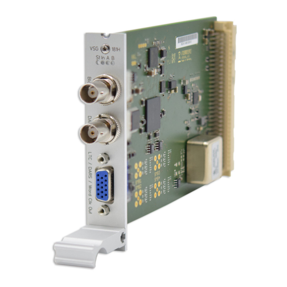
Page 10: Ims-Vsg181H Module Connectors And Indicators
5 IMS-VSG181H Module Connectors and Indicators 5 IMS-VSG181H Module Connectors and Indicators The numbering in the drawing above relates to the relevant subsection in this chapter. IMS-VSG181H Date: March 2, 2022... -
Page 11: Status Leds
5.1 Status LEDs Statusanzeige LED "St": Status of IMS-VSG181H in operating system St In A B LED "In": Status of synchronization against reference signal LED "A": Status of "Black Out" output LED "B": Status of "LTC" output The status LEDs "A" and "B" only provide information about whether the outputs have been enabled and properly configured in the LANTIME Web Interface. - Page 12 IMS-VSG181H is synchronized against reference signal, but module oscillator is not yet warmed up Yellow IMS-VSG181H is not yet synchronized against the reference signal, but a signal has been found IMS-VSG181H cannot find a stable reference signal and therefore cannot be synchronized ———————————————————————————————————————————————–...
-
Page 13: Black Out Output
5.3 DARS Output (Unbalanced) Output Signal: DARS (Unbalanced) Signal Level: TTL, 2.5 V termination Signal Type: Digital audio with sample rate of 44.1 kHz or 48 kHz Connector Type: BNC Connector, Female Cable: Coaxial Cable, Shielded Date: March 2, 2022 IMS-VSG181H... -
Page 14: D-Sub 15-Pin Multi-Output
5 IMS-VSG181H Module Connectors and Indicators 5.4 D-Sub 15-Pin Multi-Output The 15-pin D-Sub connector is used to output a vari- ety of balanced signal types: • LTC (Linear Time Code), Balanced • DARS (Digital Audio Reference Signal), Bal- anced • Word Clock Output Pin Layout Pin No. -
Page 15: Ltc Output
- 1/32, 1/16, 1/8, 1/4, 1/2, 1, 2, 4, 8, 16, 32 - Frequency range: 1.378125 kHz to 1.4112 MHz At sample frequency 48 kHz - 1/32, 1/16, 1/8, 1/4, 1/2, 1, 2, 4, 8, 16, 32 - Frequency range: 1.5 kHz to 1.536 MHz Date: March 2, 2022 IMS-VSG181H... -
Page 16: Before You Start
6.1 Contents of Delivery Unpack the IMS-VSG181H carefully and check the contents of the delivery against the enclosed packing list to ensure that no parts are missing. If any of the listed items are missing, please contact our sales department: sales@meinberg.de... -
Page 17: System Installation
Operating System, the configuration of some IMS modules may be reset to factory defaults! The NTP service and access to the web interface will be unavailable while the CPU is not installed. Management and monitoring functions will also be disabled. Date: March 2, 2022 IMS-VSG181H... -
Page 18: Installation Of Hot-Pluggable Ims Modules
Ensure that the module is securely seated in the connector block inside the chassis before you fasten the two screws. The installed module is now ready for use. Locations of fixture screws in a 1RU IMS system IMS-VSG181H Date: March 2, 2022... -
Page 19: Data And Signal Cables
7.3 Data and Signal Cables Coaxial Cable The IMS-VSG181H module provides one BNC connector for outputting an analog bi-level or tri-level sync signal, and one BNC connector for outputting a digital DARS signal. The signal outputs should be connected to your receiver device using coaxial cable with the proper char- acteristic impedance and adequate shielding. -
Page 20: Configuration And Setup Via Web Interface
This chapter describes the initial setup of a IMS-VSG181H using the Web Interface. The IMS-VSG181H is configured by selecting the menu I/O Config Output Configuration in the Web Interface. The configuration options addressed in this chapter represent a IMS-VSG181H with Firmware Version V1.11 running under LANTIME OS Version 7.04. IMS-VSG181H... -
Page 21: Output 1: Black Out
"720p 59.94 Hz" (Tri-Level Sync, SMPTE ST 296) "1080i 59.94 Hz" (Tri-Level Sync, SMPTE ST 274) Vertical Offset: Approximate configuration of phase offset in lines Horizontal Offset: Fine adjustment of phase offset in 10 ns increments Date: March 2, 2022 IMS-VSG181H... - Page 22 Use Local Time If the IMS LANTIME server is being operated as a PTP Offset from PTP slave, enabling this option will cause the IMS-VSG181H TLV if Running to incorporate any local time offset information in PTP Slave Mode: included in TLVs from the master clock for generating the signal and time codes.
-
Page 23: Output 2 & 4: Dars
You can use this field to define a custom label for the output, or you can leave the field blank. ——————————————————————————————————————————————– Please note: Output 4 is a "follower" port whose output is solely controlled by the configuration for Output 2 above. Date: March 2, 2022 IMS-VSG181H... -
Page 24: Output 3 & 6: Ltc
If this option is enabled, the parity bits will not be integrated into Encoding: the LTC data. This may be necessary for compatibility reasons. Label: You can use this field to define a custom label for the output, or you can leave the field blank. ——————————————————————————————————————————————– IMS-VSG181H Date: March 2, 2022... -
Page 25: Output 5: Word Clock
The frequency of the output signal is thus calculated as: Base Sampling Rate * Scale = Output Frequency Label: You can use this field to define a custom label for the output, or you can leave the field blank. ——————————————————————————————————————————————– Date: March 2, 2022 IMS-VSG181H... -
Page 26: Misc
8 Configuration and Setup via Web Interface 8.5 Misc ——————————————————————————————————————————————– Time Zone: This can be used to set the time zone of the IMS-VSG181H module. ——————————————————————————————————————————————– IMS-VSG181H Date: March 2, 2022... -
Page 27: Troubleshooting
Our Technical Support team will be pleased to help you with any problems that you may be having with your Meinberg IMS-VSG181H. However, before you contact our Technical Support team, it is advisable to read this chapter through first to see if your problem might be more quickly resolved with one of the solutions below. -
Page 28: Your Opinion Matters To Us
10 Your Opinion Matters to Us 10 Your Opinion Matters to Us This user manual is intended to assist you in the preparation, use, and care of your Meinberg product, and provides important information for configuration and status monitoring. Be a part of the ongoing improvement of the information contained in this manual. Please contact our Technical Support team if you have any suggestions for improvements or technical questions that are relevant to the manual. -
Page 29: Rohs And Weee
WEEE-compliant fashion, it must be returned to the manufacturer. Any transportation ex- penses for returning this product (at end-of-life) must be covered by the end user, while Meinberg will bear the costs for the waste disposal itself. Date: March 2, 2022... -
Page 30: List Of Abbreviations
National Television Standard Committee Network Time Protocol Phase Alternating Line Redundant Switch Control unit Pulse per Second SMPTE Society of Motion Picture and Television Engineers Transistor–Transitor Logic VITC Vertical Interval TimeCode Web-UI Web User Interface IMS-VSG181H Date: March 2, 2022...
Need help?
Do you have a question about the IMS-VSG181H and is the answer not in the manual?
Questions and answers