Table of Contents
Advertisement
Quick Links
Advertisement
Table of Contents

Related Manuals for Meinberg TCR180PEX-EL


Summary of Contents for Meinberg TCR180PEX-EL
- Page 1 MANUAL TCR180PEX-EL EL/FO-In 6th May 2021 Meinberg Funkuhren GmbH & Co. KG...
-
Page 3: Table Of Contents
..........11.3.1 Format of the Meinberg Standard Time String . - Page 4 ......... . 12 RoHS and WEEE 13 Declaration of Conformity Date: 6th May 2021 TCR180PEX-EL...
-
Page 5: Imprint
1 Imprint 1 Imprint Meinberg Funkuhren GmbH & Co. KG Lange Wand 9, 31812 Bad Pyrmont / Germany Phone: + 49 (0) 52 81 / 93 09 - 0 Fax: + 49 (0) 52 81 / 93 09 - 230 Internet: https://www.meinbergglobal.com... -
Page 6: Introduction
The TCR180PEX-EL is used for synchronization of directly connected systems and can be equipped with a wide range of signal outputs for various applications. Possible output options of the TCR180PEX-EL are time code, frequency and pulse as well as relay outputs for status and TimeSync. -
Page 7: Safety Instructions For Building-In Equipment
Meinberg Funkuhren shall not be responsible for any damage arising due to non-observance of these regulations. -
Page 8: Used Symbols
Dieses Produkt fällt unter die B2B Kategorie. Zur Entsorgung muss es an den Hersteller übergeben werden. This product is handled as a B2B category product. In order to secure a WEEE compliant waste disposal it has to be returned to the manufacturer. Date: 6th May 2021 TCR180PEX-EL... - Page 9 This manual is intended exclusively for electricians or persons trained by an electrician who are familiar with the applicable national standards and safety rules. Installation, commissioning and operation of this device may only be carried out by qualified personnel. TCR180PEX-EL Date: 6th May 2021...
-
Page 10: Safety Hints Tcr180Pex-El
3.3 Safety Hints TCR180PEX-EL This building-in equipment has been designed and tested in accordance with the requirements of Standard DIN EN 62368-1 "Audio/video, information and communication technology equipment - Part 1: Safety requirements). During installation of the building-in equipment in an end application (i.e. PC) additional requirements in accordance with Standard DIN EN 62368-1 have to be taken into account. -
Page 11: Prevention Of Esd Damage
ESD protective covers, which are extremely wrinkled or even have holes, no longer protect against electrostatic discharge. ESD protective covers must not be low-resistance and metallically conductive if a lithium battery is installed on the assembly. TCR180PEX-EL Date: 6th May 2021... -
Page 12: Cabling
There is a Danger of explosion if the lithium battery is replaced incorrectly. Only identical batteries or batteries recommended by the manufacturer must be used for replacement. The waste battery has to be disposed as proposed by the manufacturer of the battery. Date: 6th May 2021 TCR180PEX-EL... -
Page 13: The System Tcr180Pex-El
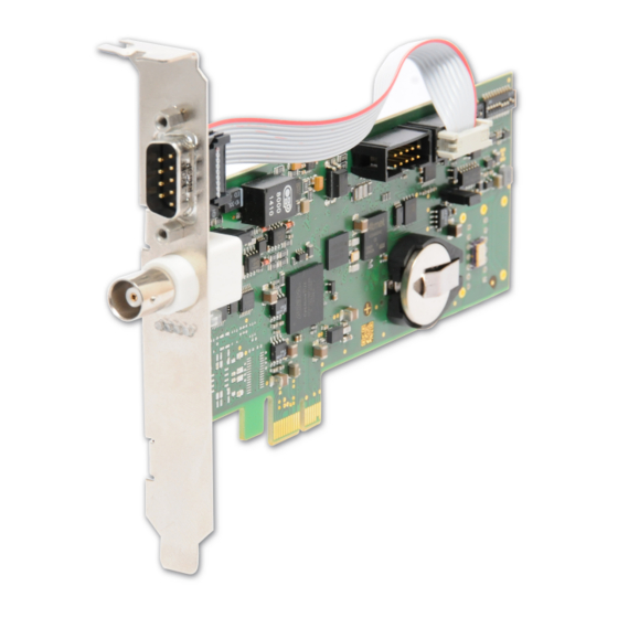
The TCR180PEX-EL is designed as a "low profile" plug-in card for PCs with PCI Express interface and is equipped with a card holder in standard height at delivery, but can be converted for operation in "low profile"... -
Page 14: Return Of Equipment
4.4 Return of Equipment All parts and components of your Meinberg system may only be repaired by Meinberg. In the event of a malfunction, the customer must contact our support service and never attempt to repair the device himself. To request a device repair service, call Meinberg Technical Support to check shipping options and obtain the Return Material Authorization (RMA) number for shipping. -
Page 15: Front Connectors Tcr180Pex-El
5 Front Connectors TCR180PEX-EL 5 Front Connectors TCR180PEX-EL TCR180PEX EL-FO TCR180PEX-EL Date: 6th May 2021... -
Page 16: Comx Timestring - Rs-232
5.1 COMx Timestring - RS-232 Data transfer: serial Baudrate/framing: 19200 / 8N1 (default) Timestring: Meinberg Standard (default) Assignment: Pin 2: RxD (receive) COM x Pin 3: TxD (transmit) Pin 5: GND (ground) Connection type: D-SUB male 9pin. Cable: data cable (shielded) PC connector 1:1 Signals like PPS, PPM, etc. -
Page 17: Tcr180Pex-El - Status Leds
LED 2: green: TCR180PEX-EL receives a valid time code at the input red: TCR180PEX-EL does not receive a valid time code at the input yellow: TCR180PEX-EL is synchronized to a multi.ref. source yellow/green (blinking): Holdover mode (Multi.Ref.), time code available yellow/red (blinking): Holdover mode (Multi.Ref.), time code not available... -
Page 18: Functional Description Of Receiver
So care must be taken that the on-board clock has been set to the correct date. The on-board date and time can be adjusted by sending a Meinberg Standard Time string to the serial interface COM0, or via the PCI bus by using the utility programs included in the driver software package. - Page 19 The associated settings can be changed using the configuration software shipped with the driver packages. Most IRIG codes don’t include an announcement flag for the DST change, or for the of a leap second, so the TCR180PEX-EL will switch into free running mode on such event, and resynchronize a few seconds later. TCR180PEX-EL...
-
Page 20: Fiber Optic Fo Input
Like IEEE 1344 - with UTC offset to be applied reversely 6.1 Fiber Optic FO Input The TCR180PEX-EL synchronizes by using pulse width modulated (DC Level Shift) time codes, IRIG-A/B/G, AFNOR NF S-87500, IEEE C37.118 or IEEE 1344. These are transmitted to the ST connector (fiber optic input) via a fiber optic cable. -
Page 21: Optocoupler Input
Pulse each minute (PPM), active HIGH, pulse duration 200 msec 6.2.3 Asynchronous serial port The TCR180PEX-EL has two serial interfaces COM0 (standard port) and COM1 (multi ref. port). At delivery the (COM0) is provided on the slot bracket. The interface (COM1) can optionally be used via a second D-SUB-9 connector. -
Page 22: Time Capture Inputs
If the buffer memory overflows, a message ("** capture buffer full" is output, if the time interval between two events at the same input is too short, the message "** capture overrun" is displayed and sent. Date: 6th May 2021 TCR180PEX-EL... -
Page 23: Before You Start
TCR180PEX-EL low-profile card holder Unpack the TCR180PEX-EL carefully and check the scope of delivery against the enclosed packing list to ensure that no parts are missing. If any of the listed items are missing, please contact our sales department: sales@meinberg.de Check the system for shipping damage. -
Page 24: Pre-Setting - Standard And Multiref Port
If another signal is to be led out, the corresponding switch of the DIP 1 block must be switched to ON before installing the TCR180PEX-EL. The table below shows the pin assignment of the connector and the assignment of the individual switches in the DIP 1 block. - Page 25 DIP 7 must be OFF / DCLS out (B) RS422 DIP 3 must be OFF PPO_0 (PPS) out PPO_2 (DCF) out DIP 6 must be OFF DCLS out (A) RS422 DIP 9 must be OFF TCR180PEX-EL Date: 6th May 2021...
- Page 26 The default settings of the pulse outputs of the TCR180PEX-EL are set as follows: PO_0: PPS Out - Pulse Per Second PO_1: PPM Out - Pulse Per Minute Date: 6th May 2021 TCR180PEX-EL...
- Page 27 RS232 TxD1 out RS232 PO_1 (PPM) out DIP 10 must be OFF 10MHz out DIP 5 must be OFF + DCLS in optocoupler - DCLS in optocoupler PO_0 (PPS) out not used only PEX-EL Version TCR180PEX-EL Date: 6th May 2021...
-
Page 28: Installing The Tcr180Pex-El
The TCR180PEX-EL is not hot-pluggable. Please switch off the PC before installation. Remove the bracket of the PCIx slot with a suitable tool and plug in the TCR180PEX-EL carefully. Tighten the bracket of the card and close the computer case again Connect all necessary cable connections. -
Page 29: Configuration Of Tcr180Pex-El
IRIG telegram containes only the day of year (1...366) instead of a complete date. To ensure correct function of TCR180PEX-EL, the date stored in the realtime clock of the board must be set when using IRIG codes therefore. This setting can be done by a terminal software also. -
Page 30: Firmware Updates
The contents of the program memory will not be modified until the loader program has sent the command to erase the flash memory. So if the button has been pressed accidentally, the system will be ready to operate again after the computer has been turned off and then on again. Date: 6th May 2021 TCR180PEX-EL... -
Page 31: Technical Specification Tcr180Pex-El
10 Technical specification TCR180PEX-EL 10 Technical specification TCR180PEX-EL Dimensions: 163 mm 6.41 inch 151 mm 5.96 inch RECEIVER INPUT: DC level shift input (fiber optic) optical input power: min.3 W optical connector: ST connector for GI 50/125 m or GI 62.5/125 m, gradient fiber... - Page 32 flow and generates a reset in case of error detection Initialization: Software and realtime clock can be set by a serial Meinberg Standard Telegram via COM0 or the PCI-Express bus Date: 6th May 2021...
- Page 33 10 Technical specification TCR180PEX-EL Bus-Interface: Single lane (x1) PCI Express (PCIe) Interface compatible to PCI Express specification r1.0a Data format: binary, byte serial Power supply: +3.3 V DC, 250 mA +/- 10 mA Power supplies provided by PCI Express interface Board dimension: "low profile"...
-
Page 34: Technical Appendix Tcr180Pex-El
Hundreds of different time codes were formed, some of which were standardized by the "Inter Range Instrumentation Group" (IRIG) in the early 60´s. The TCR180PEX-EL supports decoding and generating of IRIG-A, IRIG-B, IRIG-G, AFNOR NF S87-500, IEEE C37.118 and IEEE 1344. -
Page 35: Time Code Format
11 Technical appendix TCR180PEX-EL 11.2 Time code Format 11.2.1 IRIG Standard Format TCR180PEX-EL Date: 6th May 2021... -
Page 36: Afnor Standard Format
11.2.2 AFNOR Standard Format Date: 6th May 2021 TCR180PEX-EL... -
Page 37: Time Strings
11.3 Time Strings 11.3.1 Format of the Meinberg Standard Time String The Meinberg Standard Time String is a sequence of 32 ASCII characters starting with the STX (start-of-text) character and ending with the ETX (end-of-text) character. The format is: <STX>D:dd.mm.yy;T:w;U:hh.mm.ss;uvxy<ETX>... -
Page 38: Format Of The Meinberg Capture String
11.3.2 Format of the Meinberg Capture String The Meinberg Capture String is a sequence of 31 ASCII characters terminated by a CR/LF (Carriage Return/- Line Feed) combination. The format is: CHx_tt.mm.jj_hh:mm:ss.fffffff <CR><LF> The letters printed in italics are replaced by ASCII numbers whereas the other characters are part of the time string. -
Page 39: Format Of The Uni Erlangen String (Ntp)
11 Technical appendix TCR180PEX-EL 11.3.3 Format of the Uni Erlangen String (NTP) The time string Uni Erlangen (NTP) of a GPS clock is a sequence of 66 ASCII characters starting with the STX (start-of-text) character and ending with the ETX (end-of-text) character. The format is: <STX>tt.mm.jj;... - Page 40 ‘E’ east of Greenwich ‘W’ west of Greenwich hhhh altitude above WGS84 ellipsoid in meters leading signs are replaced by a space character (20h) <ETX> End-Of-Text, ASCII Code 03h Date: 6th May 2021 TCR180PEX-EL...
-
Page 41: Format Of The Sat Time String
11 Technical appendix TCR180PEX-EL 11.3.4 Format of the SAT Time String The SAT Time String is a sequence of 29 ASCII characters starting with the STX (start-of-text) character and ending with the ETX (end-of-text) character. The format is: <STX>dd.mm.yy/w/hh:mm:ssxxxxuv<ETX> The letters printed in italics are replaced by ASCII numbers whereas the other characters are part of the time string. -
Page 42: Format Of The Computime Time String
(01..07, 01 = monday) hh:mm:ss the current time: hours (00..23) minutes (00..59) seconds (00..59, or 60 while leap second) <CR> Carriage Return, ASCII Code 0Dh <LF> Line Feed, ASCII Code 0Ah Date: 6th May 2021 TCR180PEX-EL... -
Page 43: Format Of The Spa Time String
11 Technical appendix TCR180PEX-EL 11.3.6 Format of the SPA Time String The ABB SPA Time String is a sequence of 32 ASCII characters starting with the characters ">900WD" and ending with the <CR> (Carriage Return) character. The format is: >900WD:jj-mm-tt_hh.mm;ss.fff:cc<CR>... -
Page 44: Format Of The Racal Standard Time String
(00..99) month (01..12) day of month (01..31) hh:mm:ss the current time: hours (00..23) minutes (00..59) seconds (00..59, or 60 while leap second) <CR> Carriage Return, ASCII code 0Dh Date: 6th May 2021 TCR180PEX-EL... -
Page 45: Format Of The Ion Time String
11 Technical appendix TCR180PEX-EL 11.3.8 Format of the ION Time String The ION time string is a sequence of 16 ASCII characters starting with the SOH (Start of Header) ASCII controll character and ending with the LF (line feed, ASCII Code 0Ah) character. The format is: <SOH>ddd:hh:mm:ssq<CR><LF>... -
Page 46: Pci Express (Pcie)
PCI Express x16 slot for example uses sixteen lanes providing a data volume of 4 GB/s. For comparison: when using conventional PCI the maximum data transfer rate is 133 MB/s, PCI-X allows 1 GB/s but only in one direction respectively. Date: 6th May 2021 TCR180PEX-EL... -
Page 47: Content Of The Usb Stick
11.5 Content of the USB stick Besides this manual, the provided USB stick includes a setup program for the monitor software MBGMON. This utility can be used to configure Meinberg re- ceivers via their serial ports and to display status information of the module. -
Page 48: Rohs And Weee
Any transportation expenses for return- ing this product (at its end of life) have to be incurred by the end user, whereas Meinberg will bear the costs for the waste disposal itself. Date: 6th May 2021... -
Page 49: Declaration Of Conformity
13 Declaration of Conformity 13 Declaration of Conformity Konformitätserklärung Doc ID: TCR180PEX-EL/FO-In-2021-05-06 Hersteller Meinberg Funkuhren GmbH & Co. KG Manufacturer Lange Wand 9, D-31812 Bad Pyrmont erklärt in alleiniger Verantwortung, dass das Produkt, declares under its sole responsibility, that the product...
Need help?
Do you have a question about the TCR180PEX-EL and is the answer not in the manual?
Questions and answers