Table of Contents

Related Manuals for FASTERHOLT FM4400


Summary of Contents for FASTERHOLT FM4400
- Page 1 User Manual & (EN) 10-11-2021 Spare Parts Catalogue Irrigator FM4400 Fasterholt Maskinfabrik A/S Telephone: +45 97 18 80 66 Ejstrupvej 22 Telefax: +45 97 18 80 40 7330 Brande E-mail: mail@fasterholt.dk Denmark Web: www.fasterholt.dk...
-
Page 2: Table Of Contents
Contents Declaration of Conformity General safety Operating instructions for Fasterholt FM 4550 Product labelling Symbols Operating instructions Starting your irrigator Preparing the machine for irrigation Preparing the machine after irrigation Maintenance Preparation for winter Faults on the Irrigator Setting the gun... -
Page 3: Declaration Of Conformity
Declaration of Conformity EEC Declaration of conformity Manufacture (name and Fasterholt Maskinfabrik A/S address): Adresse: Ejstrupvej 22, CVR: 58 83 28 12 Fasterholt TEL: +45 97 18 80 66 Ort: 7330 Brande FAX: +45 97 18 80 40 Country: Denmark E‑Mail:... -
Page 4: General Safety
― STAND ASIDE when the gun is operating. ― WARNING against contact with overhead power lines with the Your new Fasterholt Irrigator is a Danish built machine, but even the machine or water jet. Avoid irrigation on or near power lines. -
Page 5: Product Labelling
Product labelling Symbols The following symbols are used in this product and the following documentation. WARNING Indicates a potentially hazardous situation. Failure to avoid the situation may result in death or serious injury. SMØRING LUBRICATION Indicates lubrication is required as per the service description HUSK efterspænding af hjulbolte... -
Page 7: Operating Instructions
Operating instructions Starting your irrigator Move the machine to the field in the transport position. When the Unwind the machine with the brake applied sufficiently to keep the hose machine is at the crop to be irrigated, disconnect the tractor from the tight on the drum at all times with the electric brake. -
Page 8: Preparing The Machine After Irrigation
Rain. On some other models, gears are selected according to the The machine is easily emptied with air (only done with special compressors). machine instructions. When starting irrigation, see the section that refers to the operat- Contact Fasterholt Maskinfabrik A/S if necessary. ing instructions for PROGRAM RAIN. -
Page 9: Faults On The Irrigator
Faults on the Irrigator REMEMBER !! Before unwinding the hose: Check the following before calling a technician: Open the filter coupling. Open the valve in the base of the turbine. 1. If the machine is irrigating, but not moving. Check that machine is in gear. Check if it is performing pre-irrigation or post-irrigation. -
Page 10: Technical Data
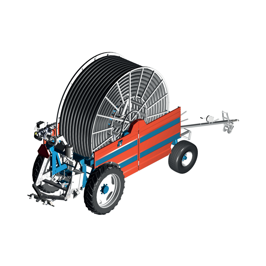
Technical data 8. Data for FM 4400 Hose PEMD 100 mm: Capacity up to 55 m3 - hose length from 200 to 550 m. Hose PEMD 110 mm: Capacity up to 75 m3 - hose length from 200 to 450 m. Wheel size: Rear wheels: 12.4"x36"... -
Page 11: Nelson Sr 150
Nelson SR 150 is factory-adjusted to Danish conditions and ready to use after the following three steps: Select and install the nozzle size that best suits your application. Performance data for the different sizes are shown in the table below. Adjust the stop on the part circle to obtain the desired irrigation angle. - Page 13 Pressure sensor Functions: Stop sensor Speed regulator Speed sensor Pre- and Post-irrigation Motor 1, regulating motor 4 different speeds on sections of the lane Motor 2, stop motor Clock Slow start of turbine Setting the start time Slow opening of inlet Stop time is shown on the display Water volume + spreading width Length of hose...
- Page 14 Short instructions for use Move machine to a new lane. Display shows start and stop time. Pull hose out to end of the lane. (e.g. 250 m) Display now shows stop after 9h 20m. Press the "+" or "-" key to set the speed. Speed can be adjusted during irrigation.
- Page 15 Standard menu: Standard display SPEED Speed. Can be changed at any time during irrigation using the "+" and "-" keys. ZONE Current zone 1...4, with corresponding speed. The speed cannot be changed. (Zone active) DOSE The dose is calculated from the speed and constants and shows the current number of mm for irrigation. As SPEED increases, DOSE decreases.
- Page 16 MENU 4 CURR. SPEED Shows the current speed. That is, the speed at which the machine is moving now. This can be used to find how fast the machine can move. The current speed may differ slightly from the set speed, especially at the start. This does not matter, as regulation ensures that the average speed within 10 metres is correct.
- Page 17 PRE-IRRIGATION: If pre-irrigation is required, press the PRE- key. The pre-irrigation time is calculated as 8 x the time to move 1 m at the current speed. The constant can be changed individually for pre- and post-irrigation. (See constants). If pre-irrigation is selected, the machine will move forward approx. ½ m, after which the machine will stop and stand still for as long as pre-irrigation is performed.
- Page 18 There are a variety of constants that can be modified by the user. These constants will be stored for many years, even if the battery is removed. Programming procedure: Adjust the speed to 11.1 m/h to access the constants. Press the PROG key 3 times in quick succession to access and change the constants. Press the PROG key again to count forward to the constant you wish to change.
- Page 19 MACHINE DATA...
- Page 20 Troubleshooting: The turbine does not start when the START key is pressed. Answer: The magnet at the stop sensor is not in position or the sensor or sensor cable is damaged. Stop sensor: The mark must be on when the magnet is in position and off when the magnet is removed. See Menu 3. A damaged cable can be assembled in an epoxy moulded assembly or with shrinkable tubing and glue.
- Page 21 GSM-2G Functions Modem Easy installation on PR10-12 Low power consumption • Dual band 850/900/1800/1900 MHz • GPRS multi slot class 12/10 Total 10 mA consumption, PR10-12 and GSM-2G • GPRS mobile station class B Visible status LED • Compliant to GSM phase 2/2+ Class 4 (2 W @850/900 MHz) Supplied with Class 1 (1 W @1800/1900MHz)
- Page 22 How to start the system: Disconnect the battery fromthe electronics. Insert the SIM card in a regular mobile phone and change the pin code to 1111. Try sending and receiving an SMS to see whether the SIM and account work as intended. Note that SIM card MUST support 2G.
- Page 23 General instructions for use Standard display Standard display, ZONE irrigation is selected. Press the MENU key 1 time to display menu 2 Press the MENU key 2 times to display menu 3 Press the MENU key 3 times to display menu 4 Press the MENU key 4 times to display menu 5 Press the MENU key 5 times to display menu 6 (Only if GSM is selected)
- Page 24 MENU 3 PRESSURE SENSOR Shows that the pressure is high when block is lit. The machine can only move when the pressure is high. If no pressure sensor is fitted (machine data 14 = 0), the machine will move regardless of pressure status. The machine can be fitted with analogue pressure sensors.
- Page 25 MENU 5 SIGNAL GSM signal strength. NETWORK GSM network. First number on "SMS" list. Second number on "SMS" list. See GSM chapter for details. START: The turbine can only start if the magnet is aligned with the end stop sensor (or end stop sensors). See menu 3 for control of the STOP SENSOR.
- Page 26 Status messages in display STATUS Machine has not been started, anyway speed pulses is received and it is trying to maintain EMERGENCY: the speed requested. The machine is irrigating, and everything is working properly. RUNNING: Water pressure is below pressure switch treshold. Machine acts depending on Machine data. LOW PRESSURE: Operator has pressed START key, and start sequens is in process.
- Page 27 FM4300 & FM4300H = 73.5 mm (2 magnets) FM4300 & FM4300H = 38.8 mm (4 magnets) FM4400 & FM4400H = 46.2 mm (4 magnets) Old Rear axle assembly FM4400 & FM4400H = 46.0 mm (4 magnets) New Rear axle assembly FM4500 &...
- Page 28 Program Rain can be set to 2 different types of sensors. See Machine Data #16 Sensor One is a round sensor with 4 built-in sensors and can only be used for rollers with 1 magnet. When the battery is connected, the display shows the following for 2 seconds: VERSION n.n0.
- Page 29 Combining the various constants: The machine will always be able to run with the factory-set constants. However, there will be different conditions from farm to farm and from machine to machine. Many requests can be met by changing the constants. Slow start-up of turbine.
- Page 30 GSM-2G is a GSM modem made for PR10-12. The machine can be started, stopped or queried about status by sending an SMS. Commands Start Starts the machine. Stop Stops the machine Speed ### Set the desired speed 3 to 400 m/h Status Returns the current machine status.
- Page 31 Modem has LED to indicate status. Green Switched off - Searching the network Flashes quickly - No SIM card in modem - Incorrect PIN code - No GSM network available STANDBY (Registered on network) Flashes slowly Connection (TALKING) When an SMS is received, the display shows: Receiving an SMS, sender's phone number and 40 characters of message.
-
Page 32: Spare Parts
Spare parts... - Page 33 Item no. Part no. Description Comments 1010107-3 Front hose guide 1761026 Shaft 761025 Shaft 761023 Support roller 5/4 170 mm 1761024 Support roller 5/4 1008210 Bracket for steering wheel 1008218 Shaft 761273 Shaft 115 mm 761272 Support roller 5/4 50mm 1008215 Safety stop 1008205...
-
Page 35: Front Axle
Item no. Part no. Description Comments 1009181-6 Hub cap 1009181-5 Crown nut 1009181-4 Hub nut M18 750032210 Tapered roller bearing 1009181 1009181-3 Hub bolt M18 750032213 Tapered roller bearing 1009181-7 Sealing washer 1009185 Spindle Left 1009188 Feather key 1008198 Spacer washer for Shaft 1009183 Spindle comp with Hub 1009191... - Page 37 Item no. Part no. Description Comments 761329 Retaining ring 761293 Bushing 761282-1 Guide sleeve 761283 Guide shaft (Pin) 761284 Washer 701040 Int. Retaining ring 1008475 Sleeve for support pipe carriage 1008490 Brace for carriage 1008480 Carriage for support pipe 761023 Support roller 761025 Shaft...
- Page 38 Description Comments Description Comments M6 x 12 Int. hex M6 x 12 Int. hex M6 Plain washer M6 Plain washer M6 Lock nut M6 Lock nut Door holder Door holder M6 x 25 M6 x 25 Description Comments Description Comments M6 x 12 Int.
- Page 39 Item no. Part no. Description Comments 2003084 Side guard RB 2003092 Side guard LF 2002965 Side guard RF 2003093 Side guard LB 2003091 Chain guard R 2003089 Chain guard L 2003099 Chain guard 2003473 Edge profile 2003118 Edge profile 2003129-1 Left Hinge 2003128-1 Right Hinge...
- Page 40 2351278...
- Page 41 Item no. Part no. Description Comments 761276 Bearing 761275 Shaft 2351278 Sprocket 14050013 Locking ring 16200726 Hose clamp 1009290 HK ball with hose connector 1008260 Locking pawl 1007760 Slide plate 5 mm 1008378 Slide plate 2mm 2001491 Angle bracket 570114 Drawbar spring 763300 Ball lever...
- Page 43 Item no. Part no. Description Comments 1007545 Pressostat 1007098 Blind flange 631112 Flange gasket 1009295 Head with pipe and flange 1001095 Sealing ring 1007250 Butterfly valve 1007230 Comp motor valve 044008 M8 Lock nut 044010 M10 Lock nut 021008035 M8 x 35 Steel bolt 022210040 M10 x 40 Steel set bolt 021010085...
- Page 45 Item no. Part no. Description Comments 700020 Retaining ring 761105-1 Bearing 761106 Tension roller 2006492 Belt tensioner arm 761106-1 Tension rollers with bearings 1009337 Bushing 1008355 Shaft 1009335 Pipe for bushings 902119 Brake shoe 902120 Brake block 761110 Spring 1009275 Arm for brake 761015-15 Cable roller loose...
- Page 47 040412 M12 Steel nut 044010 M10 Lock nut 040408 M8 Steel nut 021010055 M10 x 55 Steel bolt 763620 M8 x 40 Carriage bolt 763908 M8 Riplock 040416 M16 Steel nut 022216035 M16 x 35 Steel set bolt 022208040 M8 x 40 Steel set bolt B3 &...
-
Page 49: Drum
2003334 Inlet pipe 631112 Flange gasket 1001270 Stainless bushing 1007935 O-ring under stainless bushing 2002945 Hose drum FM4400 044010 10 mm Lock nut B1 & B2 763910 Riplock 10 021010045 10 x 45 mm Steel bolt 022210025 10 x 25 mm Steel bolt... -
Page 51: Stop Bar
Parts list D3 Item no. Part no. Description Comments 1007724 Nipple 1008335-1 Lever for ball valve 1009260 Stop bar 109101 Spacer 763300 Ball lever 1007510 Ball valve 1007511 Wheel chock 1007518 05401250 M12 Round washer 022212035 M12 x 35 Steel set bolt 022212055 M12 x 55 Steel set bolt 040412... - Page 53 Item no. Part no. Description Comments 1008601 Hose 3/8 x 1600 mm 1008609 Hose 3/8 x 1200 mm 1008612 Hose 3/8 x 600 mm...
- Page 55 Item no. Part no. Description Comments 1009500 Gear Comp 1009504 Retaining ring 95 mm 1009505 Sealing ring Ø60/95x10 1009506 Hollow shaft Ø40 1009507 Retaining ring 62mm 1009508 Cover Ø62 1009509 Shaft/Gear 1009510 Bolt with int. Hex M8 x 20 1009511 Washer 1009512 Spring washer...
- Page 57 Item no. Part no. Description Comments 1008966 Warning triangle 1008250 Rear drawbar comp 895630 Support ring 1008198 Spacer washer 1008195 Stop ring 1008585 Cylinder for forced steering 1008585-2 Piston rod for cylinder 1008585-1 Gasket set for cylinder 022210080 M10 x 80 Steel set bolt 761286-2 Lubrication cap 761286...
- Page 59 Item no. Part no. Description Comments 1009150 Rear drawbar 1011011 Drawbar spring 2006359-1 Release arm 68006 Rubber grip 1009250 Lever for decoupling 1005805 Holder for stop wedge 1005800 Stop wedge 1007540 Angle Cyl 1010750 Ball valve for Dual pump 1009350 Stop bolt for miswinding bar 1007514 Hose carrier...
- Page 60 762080 Solpanel sæt 762080 stykliste...
-
Page 61: Turbine
Item no. Part no. Description Comments 762080 Solar panel set 1009120 Suspension for turbine 1007655 Gun pipe with 90⁰ bend 761614 Flange gasket Gun 770145 7712781 150TR Plastic body 7712467 150TR Plastic cap 16050210 Soft hose no. per running metre 530 mm 044008 M8 Lock nut... - Page 65 Item no. Part no. Description Comments 095906 M6 Lock nut 096506029 M6 x 29 Support bolt Pinol 13000086 Upper flange turbine for top pipe 195211 O-ring Cover seal 195001 Turbine housing 096012 M12 Nut 096112 M12 Spring washer 195031 Impeller P195201 Shaft seal for turbine 195018...
- Page 66 26 31...
- Page 67 Item no. Part no. Description Comments 1007250 Butterfly valve 1007171 Motor housing for motor valve 1007175 End plug for motor valve 1007180 Motor for valve 1007190 Gear for electric motor 1007195 Gear for valve 1007185 Guard for motor valve 022206016 M6 x 16 Steel set bolt 022208030 M8 x 30 Steel set bolt...
- Page 69 Item no. Part no. Description Comments 631109 Flange gasket 522085 Flange gasket 631955 Flange gasket 1005753 Filter 021008045 M8 x 45 Steel bolt 021010095 M10 x 95 Steel bolt 022210040 M10 x 40 Steel set bolt B1 & B3 040408 M8 Steel nut B2 &...
- Page 72 9 10...
- Page 73 Item no. Part no. Description Comments 1009490 Rear axle assembly 1009482 Dipstick 1009220 Coupling hub 1009207 Base cover 1009203 Bushing 1009240 Shift fork 1009227 Compression spring 2003554-1 Bracket for rear axle assembly 1009225 Shift sleeve 1009235 Shaft 1009245 Shift arm 1009230 Shaft for coupling 1007440...
- Page 75 Item no. Part no. Description Comments 1009532 Shaft FM4400 1009533 Shims 0.3mm Ø94 Ext. 1009534 Shims 0.5mm Ø89.5 Ext. 1009535 Shims 0.35mm Ø95 Ext. 1009536 Shims 0.2mm Ø94 Ext. 1009537 Shims 1mm Ø94.5 Ext. 1009539 Crown wheel differential 1009540 Pinion differential 1009541 Shim pinion diff.
-
Page 77: Sensor
Item no. Part no. Description Comments 1009347 Bracket for sensor magnet 1008265 Pipe for end stop sensor 1007561 Dual sensor 1005535-1 Cable coupling Rear axle assembly 763782 M5 x 30 Int. hex 044005 M5 Lock nut 1007560 Sensor 034604020 M4 x 20 Machine screw 044004 M4 Lock nut 1005530... - Page 79 Item no. Part no. Description Comments 776849 Bolt 761614 Flange gasket for gun 778402 Lock nut 776548 O-ring 778475 O-ring 778462 Bolt 778401 Base piece 778461 Gasket 778373 Sealing ring 776253 Ball bearing 778405 Bearing housing 778372 Sealing ring 778400 Brake disc 778371 Brake lining...
- Page 81 Item no. Part no. Description Comments 778323-017 Retaining ring 776045 Retaining ring 776054 Ball bearing 778326 Spacer pipe 776048 Oil seal ring 778394 Switch lever 776064 777029 Washer 776714 Split pin 778197 Bolt 778282 Shaft 778409 Flat washer 778446 Pipe 778470 Spring 778417...
-
Page 83: Optional Equipment
Optional equipment... - Page 85 Item no. Part no. Description Comments 2010507 Stop for negative pressure 2010508 Over/negative pressure set 7550LAGD125/WA2 Grease cup system 1008490-1 Brace for support pipe carriage 1013860 Air hose 591197 Swivel angle 1916650202B Sleeve 2010525 Central lubrication main bearings 2010534 Central lubrication for hose guide 2001754 Base plate for tool box 762006...
- Page 87 Item no. Part no. Description Comments 1008280-1 A-frame Hydraulics 1008280 A-frame Cable 1008281-2 A-frame for hydraulics 1008281 A-frame 1008288 Hydraulic hose 1008285 Hole plate for hydraulics 761274 Spring 1302100800 Securing pin 8x45 1008283 Drawbar pin A-frame hydraulics 1302101000 Securing pin 10x45 1008287 Cylinder for A-frame 044010...
- Page 89 Item no. Part no. Description Comments 1150700018 ABA Rubber clamp 1007514 Hose carrier S1120 5.5 m cable incl. male connector 1008961 Rubber backing for socket 1008962 Rubber backing for socket 022208025 M8x25 Set bolt 1013505 11.25 m Plastic cable 095008020 M8x20 Round head int.
- Page 92 A/S FASTERHOLT MASKINFABRIK EJSTRUPVEJ 22, DK-7330 BRANDE DENMARK TEL.: +45 97 18 80 66 FAX: +45 97 18 80 40 E-MAIL: MAIL@FASTERHOLT.DK www.fasterholt.dk...
Need help?
Do you have a question about the FM4400 and is the answer not in the manual?
Questions and answers