Nortel DMS-100 Series Installation, Operation And Maintenance Manual
Meridian acd set
Hide thumbs
Also See for DMS-100 Series:
- Replacement procedures (1100 pages) ,
- Maintenance manual (762 pages) ,
- Manual (543 pages)

Related Manuals for Nortel DMS-100 Series


Summary of Contents for Nortel DMS-100 Series
- Page 1 297-2041-902 DMS-100 Family M5216 Meridian ACD Set Description, Installation, Operation, and Maintenance Manual Release 02.01 Standard February 1999...
- Page 2 The following are trademarks of Northern Telecom: Nortel, the Nortel globemark, DMS-100, Meridian.
-
Page 3: Publication History
Publication history April 1997 Release 01.02 Standard version for NA004 and up. February 1999 Release 02.01 Standard version changed from NA004 and up to CCM04 and 297–2041–902 01.01 Standard February 1999... - Page 4 Publication history 297–2041–902 02.01 Standard February 1999...
-
Page 5: Table Of Contents
Contents Publication history Chapter 1: Introduction General description 1-1 Physical characteristics 1-2 Other documentation 1-2 Chapter 2: Specifications Environmental and safety considerations 2-1 Temperature 2-1 Relative humidity 2-1 Electromagnetic interference 2-1 Atmospheric pollution 2-1 Vibration 2-2 Shock 2-2 Line engineering 2-2 Loop power 2-2 External power 2-3 Chapter 3: Operations and features... - Page 6 Contents Chapter 4: Installation Installing the M5216 4-1 Wall mounting the M5216 4-5 Chapter 5: Verification procedures Verification test routines 5-1 Maintenance 5-1 Loop check 5-1 Polarity check 5-2 Station Ringer test 5-3 Chapter 6: Replacement parts Figures Figure 3-1 M5216 keys and other components 3-2 Figure 3-2 M5216 key assignments 3-9...
-
Page 7: Chapter 1: Introduction
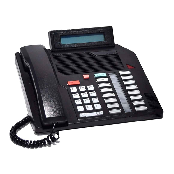
Chapter 1 Introduction General description The M5216 ACD telephone set with alphanumeric display and a headset port has been designed specifically for use with ACD applications. The M5216 is equipped with: • 14 buttons with associated liquid crystal display (LCD) indicators that may be assigned to features or line appearances •... -
Page 8: Physical Characteristics
Introduction Physical characteristics Figure 3-1 shows the main components of the M5216. The M5216 comes in three different colours: • Chameleon-grey (Engineering code NT4X44AA) • BTS light-grey (Engineering code NT4X44BA) • Black (Engineering code NT4X44CA) The Mean Time Between Failure (MTBF) for the M5216 is at least 100 years. -
Page 9: Chapter 2: Specifications
Chapter 2 Specifications The M5216 ACD set meets or exceeds the functionality standards currently attained by other members of the M5000 terminal portfolio. Environmental and safety considerations The M5216 meets the Canadian and U.S. mandatory interconnect requirements for Telephone Equipment. Temperature In the Operating State, the M5216 temperature range is 0°C to 50°C (32°F to 122°F). -
Page 10: Vibration
Specifications Vibration The M5216 ACD Set was designed to work to specifications after being subjected to the following vibrations in each of three orthogonal directions for 90 minutes: • Vibration frequency of 5 Hz to 500 Hz • Maximum half displacement 0.35mm (0.014 in) •... -
Page 11: External Power
Specifications 2-3 ± The current drawn from the loop is 16 1mA when the set is active. The ± current drawn from the loop is 10 1mA when the set is inactive. External power The M5216 requires a 16 V AC external power supply rated at 375 mA to be fully operational. -
Page 12: Chapter 3: Operations And Features
Chapter 3 Operations and features Basic operations The M5216 Meridian Business Set allows an ACD agent to answer ACD calls, place or answer non-ACD calls, and operate available ACD and non- ACD features. Supported features can be accessed using feature keys 2–14 (see Figure 3-2). -
Page 13: Description Of Features
Operations and features Description of features The M5216 Business Set (see Figure 3-1) is characterized by the following: • there are 15 fixed keys with no LCD indicators: Release key (1), Hold Key (1), volume key (1), dial pad keys (12) •... - Page 14 Operations and features 3-3 Table 3-1 Summary of M5216 keys and indicators Key or indicator Description Speaker Monitors the progress of a call without lifting the handset. Handset Used for talking on the phone—automatically selects the In Calls key when lifted. Display Shows call and installation information.
-
Page 15: Basic Features
Operations and features Basic features Every M5216 provides access to features specifically designed to assist ACD agents in performing their tasks, as well as basic business set features. Automatic Prime DN (In Calls) selection Allows the user to select the prime DN (i.e. the In Calls assigned to the first feature/line key) by going off-hook to answer a call without pressing a key. - Page 16 Operations and features 3-5 297–2041–902 02.01 Standard February 1999...
-
Page 17: Features Operation
Operations and features Features operation The following functions are provided by fixed keys on the M5216 ACD set: • dialing using dial pad keys • call Hold • call Release • adjusting the Volume Control • Handset operation and Mute •... -
Page 18: Handset Operation And Mute
Operations and features 3-7 The volume of the headset is controlled with the headset connected and the handset on-hook. The volume of the handset is controlled with the handset off-hook. If the M5216 Business Set is disconnected from the line for an extended period and then reconnected, all volume settings return to the original factory default values (Mid-point setting for alerting tones and on-hook monitoring). -
Page 19: Program Key And Local Features
Operations and features operation—refer to Automatic Call Distribution Product Guide,NTP 297– 2041–010 for details on Call Forcing). Program key and local features The M5216 has the following local features which can be set up to make it easier to use and to customize the set to meet specific user requirements. The Program key allows access to Programming mode to set up the following features: •... -
Page 20: Acd And Other Business Features
Operations and features 3-9 Figure 3-2 M5216 key assignments Feature key 8 Mute Handset When C.O. features are Feature key 7 Program enabled Key 14 Save # Feature key 6 Feature key 5 Memory Key 13 Feature key 4 Pause Key 12 Feature key 3 Feature key 11... - Page 21 3-10 Operations and features Standard business features can be used when the M5216 has been installed with a secondary DN key to make outgoing calls. These features include: • Automatic Dial (AUD) • Call Forward (CF) • Call Park (PARK) •...
-
Page 22: Headset Operations
Operations and features 3-11 Headset operations The M5216 set is compatible with several commercially available headsets that use an RJ-type modular connector (electret microphones). When a headset is connected, the hook switch is completely disabled—taking the handset off- or on-hook has no affect on the status of the call. The Handset can be used for speaking, however, and the Handset Mute function can be used for muting (see “Handset operation and Mute control”... -
Page 23: Tones
3-12 Operations and features Tones A speaker is used for alerting tones and call monitoring (on-hook dialing and listen on hold). A locally generated buzzer (500 Hz) tone is utilized for call waiting and off-hook alerting. All other telephony tones are provided by switching equipment from a Tone Card. - Page 24 Operations and features 3-13 297–2041–902 02.01 Standard February 1999...
-
Page 25: Chapter 4: Installation
Chapter 4 Installation Installing the M5216 Before installing the M5216, check the package contents and cables, as described below. To install the M5216, follow Procedure 4-1. If the M5216 needs to be mounted on the wall, follow Procedure 4-2. Unpacking or packing Use proper care while unpacking any M5216 set. - Page 26 Installation Procedure 4-1 How to install the M5216 Step Action Place the telephone in the work area (close to line cord connecting block/wall jack) upside down on soft, solid, and level work surface to prevent damage to movable keys and the telephone face.
- Page 27 Installation 4-3 Procedure 4-1 How to install the M5216 (continued) Step Action If connecting a headset, insert the headset Teladapt connector into handset jack (E in Figure 4-1). Route the headset cord through the channel provided (F) and past the restraining tabs in the base of the telephone.
- Page 28 Installation Procedure 4-1 How to install the M5216 (continued) Step Action Plug in the AC adaptor (E in Figure 4-2) into a AC 120V wall socket (F). Wait a minimum of 20 seconds to allow for proper power-up before using the Meridian Business Set. This completes the installation.
-
Page 29: Wall Mounting The M5216
Installation 4-5 Wall mounting the M5216 Your telephone set has been prepared at the factory for use on your desk. If you require the set to be positioned on a wall, follow Procedure 4-2 below. Procedure 4-2 How to mount the M5216 on the wall Step Action Turn the telephone set upside down and locate the two... -
Page 30: Figure 4-4 M5216 Base Attachment
Installation Procedure 4-2 How to mount the M5216 on the wall (continued) Step Action Reposition the wedge-shaped base (B in Figure 4-4). Press the base firmly into the bottom of the set until the plastic tabs have clicked into place. Figure 4-4 M5216 base attachment Reinsert the two screws into the screw mounts shown in... -
Page 31: Figure 4-6 Final Wall Position
Installation 4-7 Procedure 4-2 How to mount the M5216 on the wall (continued) Step Action Position the handset retainer (C in Figure 4-5) into the handset cradle. The handset retainer is included in the small package of plastic key caps which accompanies your telephone set. - Page 32 Installation 297–2041–902 01.01 Standard February 1999...
-
Page 33: Chapter 5: Verification Procedures
Chapter 5 Verification procedures Verification Test Routines This chapter describes M5216 maintenance and the following acceptance tests: • Loop check • Polarity check • Station Ringer test If the criteria outlined in Line Engineering Rules, NTP 297–2011–180, are observed, impulse or background noise and crosstalk compatibility problems are unlikely to occur. -
Page 34: Polarity Check
Verification procedures Polarity check The M5216 is polarity sensitive. If problems arise when the set is to be put into service, follow procedure 5-1. This test must also be performed on the set whenever there is an AC power failure and the set reverts to POTS mode. Procedure 5-1 How to verify the polarity Step... -
Page 35: Station Ringer Test
Verification procedures 5-3 Station Ringer Test The Station Ringer Test (SRT) tests the hardware of the M5216 ACD Set and can be performed by the installer or repairman at the site with no involvement of Central Office personnel. No incoming calls can be received for the duration of a Station Ringer test. In order to prevent prolonged line blockages, this test is limited to a 7 minute interval after which the line is automatically restored to normal and the test terminated. - Page 36 Verification procedures Procedure 5-2 How to perform the Station Ringer test Step Action or key/switch operated Response Messages Handset ON-hook. Press PDN All LCD’s ON LCD indicator ON key and dial STR (access code) using on-hook dialing. Note: All LCD indicators should be off before you start the test. The 3–14 digit access code consists of a one to seven digit number (which is assigned by the telephone company according to local preferences) followed by the last two to seven digits of the PDN assigned to the telephone to be tested.
- Page 37 Verification procedures 5-5 Procedure 5-2 How to perform the Station Ringer Test (continued) Step Action or key/switch operated Response Messages Feature key 5 LCD 5 ON Soft Reset, LCD ON Feature key 6 LCD 6 ON Soft Reset, LCD ON Feature key 7 LCD 7 ON Soft Reset, LCD ON...
- Page 38 Verification procedures Procedure 5-2 How to perform the Station Ringer Test (continued) Step Action or key/switch operated Response Messages Vol DOWN Volume down None (Test Ring Volume control. HOLD key LCDs 1–14 are ON. Soft reset 10/10 is shown on the LCD display.
- Page 39 Verification procedures 5-7 Figure 5-1 Feature/Line Key and LCD assignments Key 8 Key 7 Key 6 Key 5 Key 4 Key 3 Key 2 PDN key Key 1 Feature/ Liquid Line Crystal Keys Displays Identification (LCDs) Identification 297–2041–902 02.01 Standard February 1999...
- Page 40 Verification procedures 297–2041–902 01.01 Standard February 1999...
-
Page 41: Chapter 6: Replacement Parts
Chapter 6 Replacement parts The M5216 Business Set has few field replaceable parts. The handset, handset cord, line cord equipped with Teladapt connectors, key lenses and labels can be changed. If a Business Set fails to function properly, or if mechanical breakage occurs, do not attempt to effect repairs in the field. - Page 42 Replacement parts Table 6-1 Ordering information (continued) Description Ordering code Engineering code Meridian M5216 Basic Business Set, B0242930 NT4X44GA Chameleon-grey, made in Australia (TELSTRA) Meridian M5216 Basic Business Set, BTS light B0242930 NT4X44HA grey, made in Australia (TELSTRA) Meridian M5216 Basic Business Set, Black, B0242930 NT4X44JA made in Australia (TELSTRA)
- Page 43 Replacement parts 6-3 297–2041–902 02.01 Standard February 1999...
- Page 44 Nortel, the Nortel globemark, DMS-100, Meridian are trademarks of Northern Telecom. Information is subject to change without notice. Northern...
Need help?
Do you have a question about the DMS-100 Series and is the answer not in the manual?
Questions and answers