Advertisement
Table of Contents
- 1 Table of Contents
- 2 IMPORTANT - be Sure to Read this Section for Safe Use of the Equipment
- 3 Nomenclature
- 4 Compatible Halogen Lamp Housing
- 5 Assembly
- 6 Operation
- 7 Specifications
- 8 Control Via the Remote Connector
- 9 Troubleshooting Guide
- 10 Proper Selection of the Power Supply Cord
- 11 Lamp Housing Inspection Sheet
- Download this manual
INSTRUCTIONS
TH4
HALOGEN LAMP POWER SUPPLY UNIT
Optical Microscope Accessory
This instruction manual is for the Olympus TH4 Halogen Lamp Power Supply Unit. To ensure the safety and
obtain optimum performance and to familiarize yourself fully with the use of this unit, we recommended
that you study this manual thoroughly before operating the unit. Retain this instruction manual in an easily
accessible place near the work desk for future reference.
A X 9 9 8 2
Advertisement
Table of Contents

Related Manuals for Olympus TH4


Summary of Contents for Olympus TH4
- Page 1 HALOGEN LAMP POWER SUPPLY UNIT Optical Microscope Accessory This instruction manual is for the Olympus TH4 Halogen Lamp Power Supply Unit. To ensure the safety and obtain optimum performance and to familiarize yourself fully with the use of this unit, we recommended that you study this manual thoroughly before operating the unit.
- Page 2 Refer to your local Olympus distributor in EU for return and/or collection systems available in your country. NOTE: This product has been tested and found to comply with the limits for a Class A digital device, pursuant to Part 15 of the FCC Rules.
-
Page 3: Table Of Contents
CONTENTS IMPORTANT — Be sure to read this section for safe use of the equipment. — 1 NOMENCLATURE 2 COMPATIBLE HALOGEN LAMP HOUSING 3 ASSEMBLY 4 OPERATION 5 SPECIFICATIONS 6 CONTROL VIA THE REMOTE CONNECTOR 9-12 7 TROUBLESHOOTING GUIDE PROPER SELECTION OF THE POWER SUPPLY CORD ........................14-17 8 LAMP HOUSING INSPECTION SHEET 18, 1 9... -
Page 4: Important - Be Sure To Read This Section For Safe Use Of The Equipment
3. For operation environmental conditions, see chapter 5, “SPECIFICATIONS” on page 8. 4. Always use the power cord provided by Olympus. If no power cord is provided, please select the proper power cord by referring to the chapter “PROPER SELECTION OF THE POWER SUPPLY CORD” at the end of this instruction manual. - Page 5 Safety Symbols The following symbols are found on the power supply unit. Study the meaning of the symbols and always use the equipment in the safest possible manner. Symbol Meaning Before use, carefully read the instruction manual. Improper use could result in personal injury to the user and/or damage to the equipment.
- Page 6 Intended use This instrument has been designed to be used to observe magnified images of specimens in routine and research applications. Do not use this instrument for any purpose other than its intended use.
-
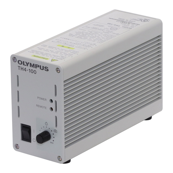
Page 7: Nomenclature
NOMENCLATURE Power Supply Unit TH4 Hand Switch TH4-HS (Optional) Brightness control knob POWER LED REMOTE LED Main switch : ON : OFF Brightness control knob Lamp ON-OFF switch Extension Cord U-RMT (Optional) Extension cord (U-RMT) Compatible halogen lamp housing Power supply unit (TH4) -
Page 8: Compatible Halogen Lamp Housing
COMPATIBLE HALOGEN LAMP HOUSING Halogen Lamp Housing · U-LH100-3 Power Supply Unit · U-LH100L-3 · IX-ILL100LH For halogen lamp housing Any lamp housings other than described above cannot be used with TH4. -
Page 9: Assembly
1. Insert the hand switch plug @ into the connector ². 2. Insert the lamp housing plug ³ into the connector |. Always use the power cord provided by Olympus. If no power cord is provided with the microscope, please select the proper power cord ³... -
Page 10: Operation
OPERATION Voltage Indication (Fig. 3 & 4) 1. Ensure that the brightness control knob @ is set to MIN (lowest voltage) ³ then set the main switch ² to “ I ” (ON). (The POWER LED ³ lights up.) 2. Turn the control knob @ toward MAX (highest voltage) to increase the voltage intensity and brighten the illumination. -
Page 11: Specifications
· Installation (overvoltage) category: II (in accordance with IEC60664-1) · Transient overvoltage: 2500 V · Temporary overvoltage: TH4-100: 1320 V (up to 5 sec); 370 V (longer than 5 sec.) TH4-200: 1440 V (up to 5 sec); 490 V (longer than 5 sec.) -
Page 12: Control Via The Remote Connector
CONTROL VIA THE REMOTE CONNECTOR Recommended DIN 8-pin plug · Connector type:TCP0500 Series (mfd. by Hosiden Electronics Co., Ltd.) Pin No. Name DIN 8-pin connector specifications Analog input for light intensity control ² Remote ON/OFF - H # Be sure not to make a mis- Vcc (13.5 V) input ³... - Page 13 Controlling the Amount of Light According to Inside the (Fig. 5) External Analog Voltage power supply unit }The amount of light can be varied between MIN and MAX by applying a DC voltage input from 0 to 5 V. 1. Connect a DC power supply as shown in Fig. 5. Do not turn on the power Control power supply yet.
- Page 14 (Fig. 6) Remote ON/OFF Operation Inside the power supply unit }The lamp can be turned off by shorting pins 4 and 2 of the DIN 8-pin connector. Vcc (13.5 V) # The external wiring should have a wire gauge of AWG28 (0.1 mm ) or 5.1 V more.
- Page 15 Detection of Failed Lamp Inside the power supply unit }Detects failed lamp and gives output alarm signal. Detection of failed lamp When lamp is normal: Open collector output is “ON” (i.e. there is a short circuit between pins 4 and 7). When lamp fails: Open collector output is “OFF”...
-
Page 16: Troubleshooting Guide
Under certain conditions, performance of the unit may be adversely affected by factors other than defects. If problems occur, please review the following list and take remedial action as needed. If you cannot solve the problem after checking the entire list, please contact your local Olympus representative for assistance. Remedy... -
Page 17: Proper Selection Of The Power Supply Cord
If no power supply cord is provided, please select the proper power supply cord for the equipment by referring to “ Specifications ” and “ Certified Cord ” below: CAUTION: In case you use a non-approved power supply cord for Olympus products, Olympus can no longer warrant the electrical safety of the equipment. - Page 18 Certification Certification Country Agency Country Agency Mark Mark Italy Argentina IRAM JET, JQA , TÜV, Japan Australia UL-APEX / MITI Netherlands Austria ÖVE KEMA Norway Belgium CEBEC NEMKO Spain Canada Sweden Denmark DEMKO SEMKO Switzerland Finland United ASTA France Kingdom U.S.A.
- Page 19 Table 2 HAR Flexible Cord APPROVAL ORGANIZATIONS AND CORDAGE HARMONIZATION MARKING METHODS Alternative Marking Utilizing Printed or Embossed Harmoniza- Black-Red-Yellow Thread (Length tion Marking (May be located on Approval Organization of color section in mm) jacket or insulation of internal wir- ing) Black Yellow...
- Page 20 Österreichischer Verband für <ÖVE> <HAR> Elektrotechnik (ÖVE) Danmarks Elektriske Materialkontroll <DEMKO> <HAR> (DEMKO) National Standards Authority of Ireland <NSAI> <HAR> (NSAI) Norges Elektriske Materiellkontroll NEMKO <HAR> (NEMKO) Asociacion Electrotecnica Y <UNED> <HAR> Electronica Espanola (AEE) Hellenic Organization for ELOT <HAR> Standardization (ELOT) Instituto Portages da Qualidade <HAR>...
-
Page 21: Lamp Housing Inspection Sheet
{If there is any ( ) mark noted, immediately stop use of the product, and contact Olympus for detailed inspections or replace the lamp housing. {If you detect an abnormality other than that listed below or with other Olympus product, also stop the use of the product and contact Olympus for detailed inspections. - Page 22 Check results (Date) Check items 1. More than 8 years have passed since original purchase or the total power ON time has exceeded 20,000 hours. 2. Lamp does not light sometimes even though the main switch is set to on. 3.
- Page 24 Manufactured by Shinjuku Monolith, 2-3-1 Nishi-Shinjuku, Shinjuku-ku, Tokyo 163-0914, Japan Distributed by 48 Woerd Avenue Waltham, MA 02453, U.S.A. 8F Olympus Tower, 446 Bongeunsa-ro, Gangnam-gu, Seoul, 06153 Korea AX9982 13 Printed in Japan 20160122 M0000...
Need help?
Do you have a question about the TH4 and is the answer not in the manual?
Questions and answers