Table of Contents
Advertisement
Advertisement
Table of Contents

Related Manuals for Renogy LYCAN 5000


Summary of Contents for Renogy LYCAN 5000
- Page 1 LYCAN 5000 Power Box RPB4835OA-48LFPA12S VERSION A0 USER MANUAL...
- Page 2 All information in the User Manual is subject to copyright and other intellectual property rights of Renogy and its licensors. The User Manual may not be modified, reproduced, or copied, in whole or in part, without the prior written permissions of Renogy and its licensors.
-
Page 3: Table Of Contents
Table of Contents Important Safety Information ....................05 Symbols Used ........................05 General Safety Information ....................05 Introduction ..........................07 Introduction ........................07 Key Features ........................07 Package Contents ........................09 Product Overview ........................10 Wiring Diagram ........................12 Installation ..........................13 Preparation .........................13 Installation ..........................14 Environment Requirements ....................17 Turning On ..........................18 Charging ..........................20 AC Charging ........................20 Solar Charging ........................21... - Page 4 Parameter Settings .........................45 Operations ..........................45 Setting Menu ........................47 Turning Off ..........................49 Capacity Expansion ........................51 Temperature Conditioning ......................54 Cooling Fan ........................54 Built-In Heater ........................54 Maintenance ...........................55 Inspection ...........................55 Cleaning ..........................55 Storage ..........................55 Emergency Responses ......................57 Fire .............................57 Flooding ..........................57 Usual Smell ........................57 Usual Noise ........................57 Technical Support ........................58 Technical Specifications ......................59...
-
Page 5: Important Safety Information
Important Safety Information The User Manual provides important installation, operation, and maintenance instructions for LYCAN 5000 Power Box. Please read the User Manual carefully before installation and operation and save it for future reference. Failure to observe the instructions or precautions in the User Manual can result in electrical shock, serious injury, or death, or can damage LYCAN, potentially rendering it inoperable. - Page 6 Important Safety Information z Please keep LYCAN out of the reach of young children. z Please use insulated tools when working on or around LYCAN. z DO NOT wear jewelry or other metal objects when working on or around LYCAN. z Please wear proper protective equipment when working on or around LYCAN.
-
Page 7: Introduction
Equipped with a Bluetooth module, the LYCAN provides access to real-time monitoring on the Renogy DC Home app. It can also be easily expanded to up to 19.2KWh with Renogy 48V 50Ah Smart Lithium Iron Phosphate Batteries, covering any applications from short term blackout protection to long term off-grid living. - Page 8 Seamless Expansion Expansion capability of up to 19.2KWh capacity. z Bluetooth Embedded Comes with Bluetooth module for real-time operation status monitoring via the Renogy DC Home App. z Designed For Outdoor Can withstand harsh outdoor environments with rain cap, rubber seals, and rugged enclosure.
-
Page 9: Package Contents
Package Contents Package Contents LYCAN 5000 Power Box × 1 Quick Guide × 1 LYCAN 5000 Power Box RPB4835OA-48LFPA12S VERSION A1 QUICK GUIDE Keys × 2 RJ45 Plug Waterproof Housing× 1 Handle Bar × 1 Handle Bar Screws × 4 M8x1.25x20mm... -
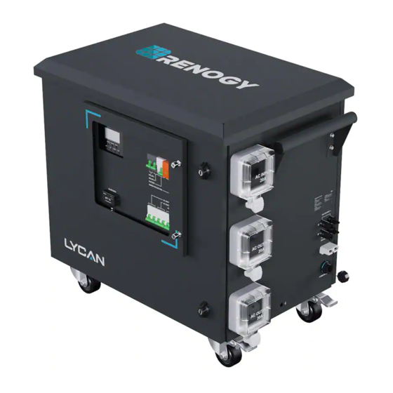
Page 10: Product Overview
Product Overview Product Overview Part Part Solar Inverter Charger Display Viewing Window (Including Indicators and Buttons) Solar Input Circuit Breaker 1 Bluetooth Module Solar Input Circuit Breaker 2 AC Output Circuit Breaker (20A) Battery Circuit Breaker AC Output Circuit Breaker (30A) Surge Protection Device AC Input Circuit Breaker (20A) Front Door Locks... - Page 11 Product Overview Part Part Solar Connector 1 Grounding Hole Anderson 120 Connector Solar Connector 2 (Including Dust Cover) RJ45 Jack Handle Bar (Pre-Installed) (Including Waterproof Housing) Back Door Locks Vent Cover Handle Bar (Installation Required) Swivel Casters...
-
Page 12: Wiring Diagram
(Wall Outlet or Generator) AC INPUT AC OUTPUT SOLAR INPUT 1 SOLAR INPUT 2 EXPANSION AC OUTPUT COMMUNICATION 48V 50AH BATTERY DC Positive DC Negative AC Output (20A AC Output (30A Renogy 48V 50Ah Smart Maximum) Maximum) Lithium Iron Phosphate Battery Communication... -
Page 13: Installation
Installation Installation Preparation 1. Inspect LYCAN for any visible damages including cracks, dents, deformation, and other visible abnormalities before installation. The connector contacts and electrical outlets shall be dry, clean, and free of any dirt and corrosion. WARNING z DO NOT use LYCAN if it appears damaged. 2. -
Page 14: Installation
INFORMATION please ensure that your changer is lithium lron phosphate compatible before use. For more information, please visit www.renogy.com c 87.7111 le, crush,puncture, or incinerate the battery. it the external contacts. - Page 15 Installation 2. Install the Handle Bar on the left side of LYCAN with the Handle Bar Screws. Make sure that the Screws are firmly tightened with the Philips Screwdriver. 3. Loosen the screws to remove the fixing bracket from LYCAN. Keep the upper screw properly for subsequent grounding cable connection.
- Page 16 Installation 5. Release the Pedal Brakes on Swivel Casters. Move LYCAN to a proper installation location. CAUTION z If transporting the Swivel Casters over wet surfaces, ensure it is no more than 2 inches (50.8 mm) deep. 6. Engage the Pedal Brakes on Swivel Casters to prevent LYCAN from moving.
-
Page 17: Environment Requirements
Installation 8. Connect the bare wire end of the grounding cable to Grounding Busbar (PE) of the AC Load Center the grounding busbar (PE) of an AC load center (not included) or a grounding rod (not included). Grounding Rod CAUTION z Please secure the grounding cable connections to the proper specification. -
Page 18: Turning On
Turning On Turning On LYCAN is off when it leaves the factory. Turn LYCAN on before charging it or using it to power appliances. 1. Open the Front Door Locks with the included Keys and rotate the wing knobs counterclockwise by 90° to open the front door. - Page 19 1 second to turn on the batteries. INFORMATION please ensure that your changer is lithium lron phosphate compatible before use. For more information, please visit www.renogy.com c 87.7111 le, crush,puncture, or incinerate the battery. it the external contacts.
-
Page 20: Charging
Charging Charging LYCAN supports both AC charging and solar charging, which can be combined for a faster charging speed. AC Charging 1. Connect LYCAN to a wall outlet or a generator (not included) with the included Power Cable. 20A AC Outlet CAUTION z The wall outlet or the outlet on the generator MUST be rated at 20A. -
Page 21: Solar Charging
Charging 4. The Solar Inverter Charger Display shows that the battery is being charged by AC, and the Solar Inverter Charger INPUTBATT OUTPUTBATT CHARGE Indicator flashes green. BYPASS 100% AC/INV CHARGE FAULT DOWN NOTE z Please close the Viewing Window and tighten the captive screws after LYCAN starts charging. - Page 22 Charging NOTE z The solar branch connectors, solar branch adapter cables, or combiner boxes (not includ- ed) might be required to connect multiple solar strings in parallel. 2. Loosen the captive screws to open the Viewing Window. 3. Push the switch up to close the corresponding Solar Input Solar Input Circuit Breaker 1 SOLAR INPUT 1 Circuit Breaker.
-
Page 23: Powering Appliances
Powering Appliances Powering Appliances LYCAN can power appliances at temporary sites, in permanent off-grid homes, and during emergencies with Power Strips, AC Load Centers, and Transfer Switches respectively. Please refer to the corresponding instructions based on actual applications. CAUTION z Please fully charge LYCAN prior to first use. Temporary Power Supply Recommended Accessories *Power Strip... - Page 24 Powering Appliances 2. Loosen the captive screws to open the Viewing Window. 3. Push the switch up to close the corresponding AC Output 20A AC Output Circuit Breaker Circuit Breaker. AC OUTPUT 20A AC OUTPUT 30A AC INPUT 30A AC Output Circuit Breaker AC OUTPUT 20A AC OUTPUT 30A AC INPUT...
-
Page 25: Off-Grid Living
Powering Appliances 4. The Solar Inverter Charger AC/INV Indicator lights up Powered by Bypass AC yellow when the appliances are powered by bypass AC. INPUT The Solar Inverter Charger AC/INV Indicator flashes yellow when the appliances are powered by LYCAN. BYPASS 100% AC/INV... - Page 26 Powering Appliances 1. Remove the cover of the AC Load Center (not included). Connect the 2 live terminals with a copper busbar (not included). 2. Connect the bare wire end of the Adapter Cable (not included) to the AC Load Center. The black live wire goes to either of the live terminals (L), the white neutral wire goes to the neutral busbar (N), and the green ground wire goes to the grounding busbar (PE).
- Page 27 Powering Appliances CAUTION z The AC Circuit Breakers and the appliances MUST be rated at 120VAC. z If the appliances are powered by LYCAN, the continuous loads shall not exceed 24A, and the noncontinuous loads shall not exceed 30A. z If the appliances are powered by bypass AC from a 20A outlet, the continuous loads shall not exceed 16A, and the noncontinuous loads shall not exceed 20A.
- Page 28 Powering Appliances 7. Push the switch up to close the 30A AC Output Circuit Breaker. AC OUTPUT 20A AC OUTPUT 30A AC INPUT 8. The Solar Inverter Charger AC/INV Indicator lights up Powered by Bypass AC yellow when the appliances are powered by bypass AC. INPUT The Solar Inverter Charger AC/INV Indicator flashes yellow when the appliances are powered by LYCAN.
-
Page 29: Emergency Backup
Powering Appliances Emergency Backup Recommended Accessories *Reliance Controls 306A Pro/ *NEMA TT-30P to Tran 2 Manual Transfer Switch NEMA L14-30R Adapter Cable METER 1 METER 2 LINE LINE WARNING z For a safe and reliable installation, it is recommended that the installation be carried out by a trained and licensed electrician. - Page 30 Powering Appliances 3. Determine the 120VAC circuits that need to be used during an emergency. Disconnect the black live wires from the corresponding AC branch circuit breakers. 4. Find the red and Branch Circuit C Wiring Diagram black wires from the Transfer Switch that are marked C, D, E, METER 1...
- Page 31 Powering Appliances 5. Remove the cover and the power inlet filler plate of the Transfer Switch. METER 1 METER 2 LINE LINE 6. Connect the green ground wire (included in the Transfer Switch) to the grounding terminal of the Transfer Switch. 7.
- Page 32 Powering Appliances 9. Replace the cover to the AC load center. Push the switches up to close all the AC METER 1 METER 2 circuit breakers in the LINE LINE Transfer Switch. Push the switches toward the center of the AC load center to close all the AC circuit breakers in the AC load center.
- Page 33 Powering Appliances 13. Push the switch up to close the 30A AC Output Circuit Breaker. AC OUTPUT 20A AC OUTPUT 30A AC INPUT 14. Move all the circuit selector switches on the Transfer Switch to the LINE position. METER 1 METER 2 LINE LINE...
- Page 34 Powering Appliances NOTE z The Manual Transfer Switch requires the selected circuits to be manually switched from grid to LYCAN during an emergency. If LYCAN is to be operate as an uninterruptible pow- er supply (UPS), please use an automatic transfer switch instead. z Please leave LYCAN plugged into a wall outlet at all times to keep it topped off...
-
Page 35: Bluetooth Pairing
2. Locate the communication hub. INFORMATION please ensure that your changer is lithium lron phosphate compatible before use. For more information, please visit www.renogy.com c le, crush,puncture, or incinerate the battery. it the external contacts. battery to temperatures above... - Page 36 Bluetooth Pairing 4. Open the DC Home app. Click "+" to search for new devices. Click "Confirm" to add the newly found device to the device list. 5. Plug the Ethernet cable back into the secondary communication port of the communication hub. Unplug the other Ethernet cable.
- Page 37 Bluetooth Pairing 8. Swipe down to refresh the device list. 9. The LINK indicator of the Bluetooth Module flashes blue.
-
Page 38: Checking Operation Status
Checking Operation Status Checking Operation Status Checking Solar Inverter Charger Operation Status Operations 1. Loosen the captive screws to open the Viewing Window. 2. The Solar Inverter Charger Display and Indicators indicate the operation status of the solar inverter charger. 3. - Page 39 Checking Operation Status Display Symbols Symbol Description Indicates that the solar inverter charger is connected to the AC Outlet Indicates that the solar inverter charger is in the wide voltage AC input mode Indicates that the solar inverter charger is connected to the solar arrays Indicates the battery level of LYCAN 0%-24%...
- Page 40 Checking Operation Status Symbol Description Indicates the load level of LYCAN 0%-24% 25%-49% 50%-74% 75%-100% Indicates that solar inverter charger is overloaded Indicates that the loads are powered by bypass AC Indicates that the buzzer of the solar inverter charger is disabled Indicates that the solar inverter charger is in warning mode Indicates that the solar inverter charger is in fault mode Indicates that the solar inverter charger is in parameter setting...
- Page 41 Checking Operation Status Symbol Description Indicates the solar charger circuit Indicates the inverter circuit Indicates the battery voltage, battery charge current, battery charge power, solar charger temperature, solar input voltage, AC input frequency, AC input voltage, AC input current, AC charger/ inverter temperature, input bus voltage, application version, model battery voltage rating, and model solar input voltage rating Indicates the battery discharge current, battery discharge power,...
- Page 42 Checking Operation Status Error Code Error Code Error Name Battery Undervoltage Warning Battery Overcurrent Software Protection Battery Not Detected Warning Battery Undervoltage Protection Battery Overcurrent Hardware Protection Battery Overvoltage Protection Battery Boost Circuit Overvoltage Hardware Protection Battery Boost Circuit Overvoltage Software Protection Solar Input Overvoltage Protection Solar Buck Circuit Overcurrent Software Protection Solar Buck Circuit Overcurrent Hardware Protection...
-
Page 43: Checking Battery Operation Status
LYCAN might not be operating properly and needs troubleshooting if the Solar Inverter Charger Display does not turn on, or the Solar Inverter Charger FAULT Indicator lights up/ flashes red. Please refer to the user manual of the solar inverter charger at renogy.com for troubleshooting instructions. - Page 44 INFO z LYCAN might not be operating properly and needs troubleshooting if the indicators of the batteries do not light up or light up/flash red. Please refer to the user manual of the bat- tery at renogy.com for troubleshooting instructions.
-
Page 45: Parameter Settings
Parameter Settings Parameter Settings The solar inverter charger is preset to operate with the batteries. While no additional programming is required, some parameters can be modified for specific applications. Operations 1. Loosen the captive screws to open the Viewing Window. 2. - Page 46 Parameter Settings 4. Press the Solar Inverter Charger ENT Button to confirm the selection. 5. Press the Solar Inverter Charger UP and DOWN Buttons to set the parameter. 6. Press the Solar Inverter Charger ENT Button to confirm the setting. 7.
-
Page 47: Setting Menu
Parameter Settings Setting Menu Parameter Parameter Name Default Setting Setting Range Code Exit Load Operating Mode SOL/UtI/SBU AC Output Frequency 60Hz Modification Not Allowed AC Input Voltage Range Modification Not Allowed Battery to Utility Setpoint 45.2V 42V-47.6V Utility to Battery Setpoint 54.8V 48V-54.8V Battery Charging Mode... - Page 48 Parameter Settings Parameter Parameter Name Default Setting Setting Range Code Battery Boost Return Setpoint 50.8V Modification Not Allowed AC Output Voltage 120V Modification Not Allowed Maximum AC Input Current 5A-20A CAUTION z Modifying the parameters outside the specified range can lead to irreversible damage to LYCAN and voids the warranty.
-
Page 49: Turning Off
Turning Off Turning Off If LYCAN is not going to be used for a long time, and neither solar nor AC power are available to keep LYCAN topped off, turn LYCAN off to prevent it from overdischarging. 1. Disconnect all the cables from LYCAN. - Page 50 Turning Off 5. Open the Back Door Locks with the included Keys and rotate the wing knobs counterclockwise by 90° to open the back door. 6. Press and hold the power button on the top of the upper battery for 3-5 seconds to turn off the batteries. 7.
-
Page 51: Capacity Expansion
Battery Cables Ethernet Cables CAUTION z ONLY connect Renogy 48V 50Ah Smart Lithium Iron Phosphate Batteries to LYCAN for capacity expansion. Connecting other brands or models of batteries to LYCAN can dam- age LYCAN and/or the batteries. z Please read the user manual of the Battery on renogy.com carefully before connecting additional Batteries to LYCAN. - Page 52 Capacity Expansion 2. Connect the UP communication ports of the latter Batteries to the LINK communication ports of the former one with the Ethernet Cables (not included). LINK CAUTION z Please use CAT5 or above Ethernet Cables. 3. Remove the Dust Cover of the Anderson Connector. 4.
- Page 53 Capacity Expansion 5. Install the included RJ45 Plug Waterproof Housing on one end of the Ethernet Cable. CAUTION z Please use CAT5 or above Ethernet Cables. 6. Connect the UP communication port of the first Battery to the RJ45 Jack of LYCAN. 7.
-
Page 54: Temperature Conditioning
Temperature Conditioning Temperature Conditioning Cooling Fan The fans are located at the bottom of LYCAN. They start operating when the temperature of the air vent rises above 131°F (55°C) and stop operating when the temperature of the air vent drops below 113°F (45°C). The thermostat is located next to the fan and displays the temperature of the air vent. -
Page 55: Maintenance
Maintenance Maintenance Inspection Please perform regular inspections following the steps below. z Examine the external appearance of LYCAN. The enclosure and connector contacts of LYCAN shall be clean, dry, and free of corrosion. z Check the external cables and connections. Replace any damaged cables and tighten any loose connections. - Page 56 Maintenance CAUTION z DO NOT expose LYCAN to extreme temperatures above 140°F (60°C). z DO NOT expose LYCAN to heat sources or direct sunlight. NOTE z If the Keys are lost, please contact us for help.
-
Page 57: Emergency Responses
Emergency Responses Emergency Responses In the event of any threat to health or safety, always begin with the steps below before addressing other suggestions. z Immediately contact the fire department or other relevant emergency response team. z Notify all people who might be affected and ensure that they can evacuate the area. WARNING z ONLY perform the suggested actions below if it is safe to do so. -
Page 58: Technical Support
Technical Support Technical Support For additional support, contact the Renogy technical support team through renogy.com/ contact-us. Have the following information available when contacting Renogy. z Owner name z Contact information z Order number z Purchase channel z Serial number z Brief description of the issue... -
Page 59: Technical Specifications
Technical Specifications Technical Specifications General Dimension 32.9 x 20.0 x 28.5 inch / 835 x 508 x 724 mm Weight 264.6 lbs. / 120 kg Operating Temperature Range 14°F~122°F / -10°C~50°C Operating Relative Humidity Range 5%~95% Storage Temperature Range 32°F~104°F / 0°C~40°C Expansion Connector Anderson 120 Connector, RJ45 Female Connector Expansion Capability... - Page 60 Technical Specifications Maximum Battery Charge Current (Solar) Maximum Battery Charge Current 100A (Total) Output Rated AC Output Voltage 120VAC Rated AC Output Frequency 50Hz/60Hz (Adjustable) Rated Output Power 3500W Peak AC Output Power 7000W...
-
Page 61: Dimensions
Dimensions Dimensions 20.61inch 32.86inch 523.6mm 834.7mm 19.74inch 28.74inch 501.5mm 730.0mm 2.06inch 52.3mm 1.97inch 50.0mm 28.55inch 725.3mm 4.17inch 106.0mm... -
Page 62: Product Schematic
Product Schematic Product Schematic Positive Busbar Grounding Busbar Surge Protection Device Negative Busbar Anderson Connector Battery Circuit Breaker RJ45 Jack Solar Input Circuit Breaker 2 Solar Input Circuit Breaker 1 BT-2 Bluetooth Module Solar Connector 1 Communication Hub Solar Connector 2 Thermostat 48V 50Ah Smart 48V 3500W... -
Page 63: Serviceable Parts
Serviceable Parts Serviceable Parts Part Number Description RIV4835CSH1S 48V 3500W Solar Inverter Charger RBT50LFP48S 48V 50Ah Smart Lithium Iron Phosphate Battery RCM-BT2 BT-2 Bluetooth Module RCM-HUB Communication Hub 2.16.0032 125A 1P Battery Circuit Breaker 2.16.0036 32A 1P Solar Input Circuit Breaker 2.16.0037 20A 2P AC Input/Output Circuit Breaker 2.16.0038... - Page 64 Serviceable Parts Part Number Description 10AWG 760mm 20A AC Input Circuit Breaker to Solar Inverter Charger Cable 2.16.0081 (Red) 10AWG 760mm 20A AC Input Circuit Breaker to Solar Inverter Charger Cable 2.16.0082 (Black) 2.16.0054 4AWG Battery to Anderson 120 Connector Cables 500mm Battery Interconnect Communication Cable 500mm Battery to Communication Hub Cable RSR28COMC-RLO5B...
- Page 65 RENOGY.COM Visit renogy.com to find the User Manual or get more support via "Contact Us". Renogy reserves the right to change the contents of this manual without notice. Your voice matters! Scan the QR code to submit your feedback on the product.
Need help?
Do you have a question about the LYCAN 5000 and is the answer not in the manual?
Questions and answers