Table of Contents
Advertisement
Available languages
Available languages
Quick Links
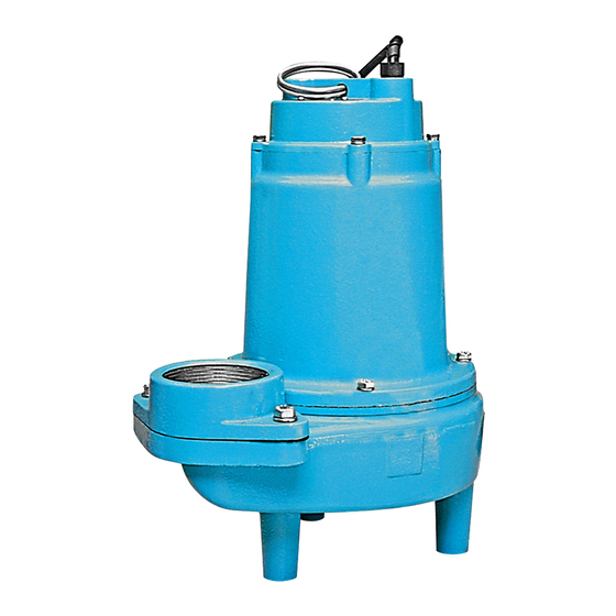
OWNER'S MANUAL
14S and 16S Series
Little Giant 14S and 16S series submersible pumps are recommended for use in
basins or lift stations and suitable for sewage wastewater transfer, and dewa-
tering. These pumps have 2 inches (50.8 mm) spherical solids handling capa-
bility. For single phase models use with approved liquid level control with
correct rating that matches marked motor input in full load amperes or service
factor amperes. For three phase pumps use with approved motor control that
matches motor input in full load amperes with overload element(s) selected or
adjusted in accordance with control instructions.
This product is covered by a Limited Warranty for a period of 3 years from the
date of original purchase by the consumer. For complete warranty information,
refer to www.littlegiant.com.
Specifications
Discharge
Model
in (mm)
2 (51)
14S
3 (76.2)
16S
3 (76.2)
SAFETY INSTRUCTIONS
This equipment should be installed and serviced by technically qualified personnel who are familiar with
the correct selection and use of appropriate tools, equipment, and procedures. Failure to comply with
national and local electrical and plumbing codes and within Little Giant recommendations may result in
electrical shock or fire hazard, unsatisfactory performance, or equipment failure.
Know the product's application, limitations, and potential hazards. Read and follow instructions carefully to
avoid injury and property damage. Do not disassemble or repair unit unless described in this manual.
Refer to product data plate(s) for additional precautions, operating instructions, and specifications.
Failure to follow installation or operation procedures and all applicable codes may result in the following
hazards:
Risk of death, personal injury, or property damage due to explosion,
fire, or electric shock.
•
Do not use to pump flammable, combustible, or explosive fluids such as gasoline, fuel oil, kerosene, etc.
•
Do not use in explosive atmospheres or hazardous locations as classified by the NEC, ANSI/NFPA70.
•
Do not handle a pump or pump motor with wet hands or when standing on a wet or damp surface, or in water.
•
When a pump is in its application, do not touch the motor, pipes, or water until the unit is unplugged or electrically disconnected.
•
If the power disconnect is out of sight, lock it in the open position and tag it to prevent unexpected application of power.
•
If the disconnect panel is not accessible, contact the electric company to stop service.
HP
Volts
Hz
1/2
115
230
200-208
60
1
230
200-208
Amps
Watts
Phase
11.6
1100
1900
11
2000
1900
6.3
1500
6.8
800
EN
English
Shut Off
PSI
ft (m)
10.8
25 (7.6)
1
15.1
35 (10.7)
3
Advertisement
Table of Contents

Subscribe to Our Youtube Channel
Related Manuals for Little Giant 14S Series


Summary of Contents for Little Giant 14S Series
- Page 1 Failure to comply with national and local electrical and plumbing codes and within Little Giant recommendations may result in electrical shock or fire hazard, unsatisfactory performance, or equipment failure.
- Page 2 SAFETY INSTRUCTIONS Specifications High voltages capable of causing severe injury or death by electrical shock are present in this unit. • To reduce risk of electrical shock, disconnect power before working on or around the system. More than one disconnect switch may be required to de-energize the equipment before servicing.
-
Page 3: Typical Installation
INSTALLATION Typical Installation INSTALLATION Typical Installation Gas Tight Gate Air Bleed “Electrical Connections” 3. Union Basin Valve Hole on page 2. Discharge 4. Check Valve 6. Intake 8. Vent 10. Caulking Hub... -
Page 4: Physical Installation
INSTALLATION Physical Installation Physical Installation Risk of damage to pump or other equipment. • Support pump and piping when assembling and when installed. Failure to do so may cause piping to break, pump to fail, motor bearing failures, etc. • If the relief hole in the discharge pipe is not provided, the pump could “air lock” and will not pump water even though it will run. -
Page 5: Electrical Connections
INSTALLATION Electrical Connections Electrical Connections Risk of severe injury or death by electrical shock. • Always disconnect the electrical power before touching the pump, discharge or electrical plug when water is present in the area. • Be certain that this pump is connected to a circuit equipped with a ground fault circuit interrupter (GFCI) device if required by code. -
Page 6: Maintenance
MAINTENANCE Periodic Service MAINTENANCE Risk of severe injury or death by electrical shock, high temperatures, or pressurized fluids. • Always unplug the pump power cord in addition to removing the fuse or shutting off the circuit breaker before working on the pump or switch. •... -
Page 7: Troubleshooting
MAINTENANCE Troubleshooting Troubleshooting Problem Probable Causes Corrective Action Pump not plugged in Plug in pump. Circuit breaker off or fuse removed Turn on circuit breaker or replace fuse. Accumulation of trash on float Clean float. Pump does not turn Float obstruction Check float path and provide clearance. -
Page 8: Replacement Parts
MAINTENANCE Replacement Parts Replacement Parts Item Description Part Number Wire Handle 114100 Cover, Housing 114051 Screw, 1/4 - 20 X 3/4 903723 Lock washer, 1/4 921103 Screw, #8-32 x 1/4” 902437 Lock washer, #8 921059 950500 Capacitor, 20mfd, 1.75” DIA/CLIP, 1.75” DIA 950503 Boot Insulating 950502... -
Page 9: Manual Del Propietario
Español SERIE 14S Y 16S Se recomienda utilizar las bombas sumergibles de las series Little Giant 14S y 16S para estanques o plantas de bombeo y son adecuadas para la transferencia de aguas residuales y drenaje. Estas bombas tienen capacidad de manejo de sólidos esféricos de 2 pulg (50.8 mm). - Page 10 INSTRUCCIONES SOBRE SEGURIDAD Especificaciones Riesgo de muerte, lesiones personales o daños materiales por explosión, incendio o descarga eléctrica. • No usar para bombear líquidos inflamables, combustibles o explosivos como gasolina, fueloil, kerosene, etc. • No usar en atmósferas explosivas ni lugares peligrosos según la clasificación de la NEC, ANSI/NFPA70. •...
- Page 11 INSTRUCCIONES SOBRE SEGURIDAD Especificaciones Riesgo de lesiones corporales, descargas eléctricas o daños al equipo. • La operación de este equipo exige instrucciones detalladas para su instalación y operación que se encuentran en este manual para su uso con este producto. Lea la totalidad del manual antes de comenzar la instalación y la operación. El usuario final debe recibir y conservar el manual para usos futuros.
-
Page 12: Instalación Típica
INSTALACIÓN Instalación típica INSTALACIÓN Instalación típica Depósito 5. Válvula de 7. Orificio de 9. Consulte “Conexiones impermeable 3. Unión compuerta purga de aire eléctricas” en la página a los gases 4. Válvula de 2. Descarga 6. Toma 8. Ventilación 10. Cubo de calafateo chequeo... -
Page 13: Instalación Física
INSTALACIÓN Instalación física Instalación física Riesgo de daños materiales por inundaciones. • Sostenga la bomba y la tubería durante el ensamblaje y cuando estén instaladas. Si esto no se realiza, la tubería se puede romper, la bomba puede tener fallas, los cojinetes del motor pueden tener fallas, etc. •... -
Page 14: Conexiones Eléctricas
INSTALACIÓN Conexiones eléctricas Conexiones eléctricas Esta unidad tiene voltajes elevados que son capaces de provocar lesiones graves o muerte por descarga eléctrica. • Cerciórese de que esta bomba esté conectada a un circuito equipado con un dispositivo interruptor de circuito de fallos de conexión a tierra si es requerido por el reglamento electrotécnico. -
Page 15: Mantenimiento
MANTENIMIENTO Servicio periódico MANTENIMIENTO Riesgo de lesiones graves o muerte por descarga eléctrica, temperaturas elevadas o líquidos presurizados. • Siempre desenchufe el cable eléctrico de la bomba y desconecte la alimentación eléctrica antes de realizar el mantenimiento de la bomba o del interruptor. •... -
Page 16: Solución De Problemas
MANTENIMIENTO Solución de problemas Solución de problemas Problema Causas probables Acción correctiva La bomba no está conectada al sumi- Conecte la bomba a un circuito dedicado que esté equi- nistro eléctrico. pado con GFCI. Disyuntor apagado o sin fusible. Encienda el disyuntor o reemplace el fusible. La bomba no se Acumulación de basura o residuos Limpie el flotante. -
Page 17: Piezas De Repuesto
MANTENIMIENTO Piezas de repuesto Piezas de repuesto Item Description Part Number Manija de alambre 114100 Cubierta y carcasa 114051 Tornillo, 1/4 - 20 X 3/4 903723 Arandela de presión, 1/4 921103 Tornillo, #8-32 x 1/4” 902437 Arandela de presión, #8 921059 950500 Capacitor, 20mfd, 1.75”... - Page 18 Para la ayuda técnica, por favor póngase en contacto: 800.701.7894 | littlegiant.com Franklin Electric Co., Inc. | Oklahoma City, OK 73157-2010 10000011131 Rev. 000 01/22 Copyright © 2022, Franklin Electric, Co., Inc. Todos los derechos están reservados.
-
Page 19: Manuel Du Propriétaire
équipements et les procédures appropriés. Le non-respect des codes électriques et codes de plomberie local et national et des recommandations de Little Giant pourrait mener à une électrocution ou un incendie, une mauvaise performance ou une défaillance de l’équipement. - Page 20 CONSIGNES DE SÉCURITÉ Spécifications Risque de mort, de blessure corporelle ou de dommage matériel en raison d’une explosion, d’un incendie ou d’une électrocution. • Ne pas utiliser pour pomper des liquides inflammables, combustibles ou explosifs comme l’essence, le mazout, le kérosène, etc. •...
- Page 21 CONSIGNES DE SÉCURITÉ Spécifications Risque de blessure, de choc électrique ou de dégâts matériels. • L’utilisation de cet équipement nécessite les instructions d’installation et d’utilisation détaillées fournies dans le présent manuel à utiliser avec ce produit. Lisez le manuel intégralement avant de procéder à l’installation et à l’utilisation du produit. L’utilisateur final doit recevoir et conserver le manuel pour consultation ultérieure.
-
Page 22: Installation Typique
INSTALLATION Installation typique INSTALLATION Installation typique Consultez Bassin étanche Clapet de la Orifice de 3. Raccord prise d'air 9. « Connexions élec- aux gaz vanne triques » page 2. Refoulement 4. Clapet de retenue 6. Entrée 8. Aération 10. Collet d’étanchéité... -
Page 23: Installation Physique
INSTALLATION Installation physique Installation physique Risque de dommages matériels dus aux inondations. • Soutenir la pompe et la tuyauterie au cours de l’assemblage et après installation. Un manquement pourrait entraî- ner la rupture des tuyaux, la défaillance de la pompe, la défaillance des paliers du moteur, etc. •... -
Page 24: Connexions Électriques
INSTALLATION Connexions électriques Connexions électriques Cet appareil contient des tensions élevées susceptibles d’entraîner par choc électrique des blessures graves ou la mort. • Assurez-vous que cette pompe est connectée à un circuit équipé d’un disjoncteur différentiel de fuite à la terre (DDFT) si le règlement l’exige. -
Page 25: Entretien
ENTRETIEN Service périodique ENTRETIEN Risque de blessure grave ou de mort par électrocution, température élevée ou liquide sous pression. • Avant d’effectuer des travaux sur la pompe ou l’interrupteur, vous devez toujours débrancher le cor-don d’ali- mentation de la pompe, en plus de retirer le fusible ou de couper le disjoncteur. •... -
Page 26: Dépannage
ENTRETIEN Dépannage Dépannage Problème Causes probables Mesure Corrective La pompe n’est pas branchée. Branchez la pompe. Disjoncteur éteint ou fusible retiré. Activez le disjoncteur ou remplacez le fusible. Accumulation de déchets sur le flot- Nettoyez le flotteur. teur. La pompe ne démarre pas Vérifiez la trajectoire du flotteur et assurez son dégage- Obstruction du flotteur. -
Page 27: Pièces De Rechange
ENTRETIEN Pièces de rechange Pièces de rechange Item Description Part Number Poignée à ressort 114100 Couvercle; boîtier 114051 Vis; 1/4 - 20 X 3/4 903723 Rondelle de blocage; 1/4 921103 Vis, #8-32 x 1/4” 902437 Rondelle de blocage, #8 921059 950500 Condensateur;... - Page 28 Pour l’aide technique, entrez s’il vous plaît en contact : 800.701.7894 | littlegiant.com Franklin Electric Co., Inc. | Oklahoma City, OK 73157-2010 Droits d’auteur © 2022, Franklin Electric, Co., Inc. Tous droits réservés. 10000011131 Rév. 000 01/22...
Need help?
Do you have a question about the 14S Series and is the answer not in the manual?
Questions and answers