Fass TITANIUM Series Installation Manual
All 1/2” fuel ports
Hide thumbs
Also See for TITANIUM Series:
- Installation manual (25 pages) ,
- Manual (20 pages) ,
- Installation manual (13 pages)
Advertisement
Quick Links
TITANIUM SERIES
INSTALLATION MANUAL
ALL 1/2" FUEL PORTS
GM 6.5L TURBO DIESEL
APPLICATION:
T S - C08 -100G
Standard Pickup Truck
(100GPH @ 5-7PSI)
1992-2000
TS-C08-165G
(165GPH @ 5-7 PSI)
*
NOTE: CAB AND CHASSIS MAY
REQUIRE MODIFICATIONS
LIFETIME
WARRANTY
A V AILABLE
FASS DIESEL FUEL SYSTEMS® / ENGINEERED EXCELLENCE
Advertisement

Subscribe to Our Youtube Channel
Related Manuals for Fass TITANIUM Series


Summary of Contents for Fass TITANIUM Series
- Page 1 GM 6.5L TURBO DIESEL APPLICATION: T S - C08 -100G Standard Pickup Truck (100GPH @ 5-7PSI) 1992-2000 TS-C08-165G (165GPH @ 5-7 PSI) NOTE: CAB AND CHASSIS MAY REQUIRE MODIFICATIONS LIFETIME WARRANTY A V AILABLE FASS DIESEL FUEL SYSTEMS® / ENGINEERED EXCELLENCE...
- Page 2 In order to qualify for the lifetime extended warranty, your product registration form and proof of purchase from an authorized dealer must be submitted to FASS Fuel Systems within 30 days of purchase. Failure to comply will void the warranty. We have the right to deny any warranty believed to be false, altered or purchased through an unauthorized or terminated dealer.
- Page 3 Dealer. If in doubt, check www.FASSRide.com. (If your purchase was made on Amazon.com, the warranty is void. Return the FASS product to the seller and get a refund). 2. It is registered within thirty (30) days of purchase. Other conditions may apply. Please see full warranty information.
- Page 4 INSTALLATION OF YOUR NEW TITANIUM FUEL SYSTEM ATTENTION: Be sure to identify the proper FASS System and fuel line configuration. For help, our product finder can be found at www.FASSride.com. Follow the instructions to see fuel line detail. Be sure the serial number on this installation...
- Page 5 8. Keep debris from entering the internals of the system during installation. Getting debris in the water separator nipple can lock up the motor. If the motor does lock up from debris call FASS for technical assistance. 9. Wear safety glasses when operating power tools such as drills and grinders or when using a punch or chisel.
- Page 6 (866) 769.3747 WARNING! Always be sure to fill the fuel tank to full after a new FASS installation. Failure to do so can result in excessive sound output, or priming issues!
- Page 7 “R" Return to Tank “R" Return to Tank Step Step 2. 2. Remove the fuel tank Step 3. Step 3. Prepare the FASS 3. 3. "H" Coolant Heater Ports "H" Coolant Heater Ports Step 4. 4. Mount the FASS 4. 4.
- Page 8 www.fassride.com TITANIUM (866) 769.3747 SIGNATURE SERIES 100 GPH or 165 GPH 5-7 PSI (Ap proximately) Note: Going over 30 PSI WILL void warranty. NOTE: WARRANTY MAY BE VOID IF SILICONE BAND IS REMOVED FROM MOTOR!! The silicone band is in place to retain motor wires, preventing damage to the electric motor.
- Page 9 www.fassride.com (866) 769.3747 CONTENTS NOTE: Owner’s Manual available for download on our website, www.FASSride.com RELAY COVER DIELECTRIC GREASE TWO (2) OR-030 OR-017 NOTE: THESE SPARE BASE O-RINGS ARE INCLUDED WITH THE KIT IN THE EVENT OF A PINCHED O-RING DURING ASSEMBLY MP-9085 RS-2002 PFB-2001C-SHORT...
- Page 10 www.fassride.com (866) 769.3747 MOUNTING PACKAGE CONTENTS TWO (2) RING TERMINALS TWO (2) PL-1005 (1)- BHF-1002 TWO (2)-PL-1004 (1)-10-300 (3) WA-2001 (1) - 46405 (1)- 10-301 (1)- 47003 FOUR (4) LOCKING (1) RS-2004 (1) FUEL SUCTION TUBE NUT 3/8"" (2)3/8 HOSE CLAMPS (1) CTMC-1001 FOUR (4) Hex Bolt 3/8”...
- Page 11 www.fassride.com (866) 769.3747 STEP 1: INSTALL ELECTRICAL HARNESS The installation of the electrical harness is done first, allowing power to be applied to the pump for lubrication purposes later in the installation. NOTE: USE SUPPLIED DIELECTRIC GREASE SPARINGLY ON ALL ELECTRICAL CONNECTIONS! BE SURE TO GREASE RELAY PIGTAIL!
- Page 12 STEP 1: INSTALL ELECTRICAL HARNESS The installation of the electrical harness is done first, allowing power to be applied to the pump for lubrication purposes later in the installation. Install the Relay Cover onto the relay on the FASS harness.
- Page 13 INSTALL ELECTRICAL HARNESS The installation of the electrical harness is done first, allowing power to be applied to the pump for lubrication purposes later in the installation. NOTE: BE SURE TO INSTALL THE SUPPLIED 10 AMP FUSE INTO THE FASS WIRING HARNESS!!
- Page 14 www.fassride.com (866) 769.3747 STEP 1: INSTALL ELECTRICAL HARNESS The installation of the electrical harness should be completed first. This will allow power to be applied to the pump during installation. Using wire stripping tool remove excess insulation off the add-a-fuse and the WH-1006-3 B.
- Page 15 Di-electric grease may be applied to prevent corrosion. RELAY Locate the fuse panel on the kick panel of the dash. Route the single red wire of the FASS harness through the firewall and to the fuse panel. F. Using a test light, locate a key-on fuse in the fuse panel. Once you have located a key-on fuse cavity, install the existing fuse in the lower fuse location on the 46405 add-a-circuit.
- Page 16 www.fassride.com (866) 769.3747 STEP 1: INSTALL ELECTRICAL HARNESS F. Route WH-1006-3 wire harness along frame rail to mounting location of pump. Completion of this step will be addressed in the Mounting Step 3.
- Page 17 www.fassride.com (866) 769.3747 STEP 2: Remove Fuel Tank Some of the photo’s are of a different application, procedures are the same.. A. Loosen both fuel tank fill and fuel tank vent clamps. (A small amount of penetrating oil can be helpful to remove these older dry connections) Remove both rubber hoses. (Save) B.
- Page 18 STEP 3: www.fassride.com (866) 769.3747 PREPARE SUCTION AND RETURN LINES A. Once the fuel tank is removed, remove the factory fuel tank sending unit. Rotate the locking ring that fastens the fuel tank sending unit to the fuel tank, counter clockwise. This will allow you to remove the fuel tank sending unit.
- Page 19 www.fassride.com STEP 3 : PREPARE (866) 769.3747 SUCTION AND RETURN LINES E. Once you have marked the location of the suction bulk head (BHF-1002) use a center punch and make a mark in the fuel tank. Then proceed to drill a 1 3/8"...
- Page 20 www.fassride.com STEP 3: (866) 769.3747 PREPARE SUCTION AND RETURN LINES G. Prepare the BHF-1002 by installing the PL-1004 fittings to both sides of the BHF-1002. Then install the ST-1005XP to the suction nipple of the BHF-1002. Fasten the 3/8's hose clamp around the suction nipple and the ST-1005P.
- Page 21 ENSURE THAT THE ALINGMENT OF THE CLAMP IS COVERING THE RETURN "R" PORT!! THIS IS VERY IMPORTANT FOR PROPER FUEL RETURN FROM THE FASS. YOU ALSO NEED TO ENSURE PROPER ALINGMENT OF THE 3/8's CLAMP FOR THE BHF-1002 NUT TO BE INSTALLED.
- Page 22 www.fassride.com STEP 3: (866) 769.3747 PREPARE SUCTION AND RETURN LINES Section 3-B INCORRECT...
- Page 23 www.fassride.com (866) 769.3747 STEP 3: PREPARE SUCTION & RETURN LINES VERY IMPORTANT: Support fuel tank on both ends allowing the natural formation of the tank to take place. Failure to perform this step can and will create an issue with less usable fuel! I.
- Page 24 www.fassride.com STEP 3: PREPARE SUCTION (866) 769.3747 AND RETURN LINES K. With the BHF-1002 tightly fastened to the fuel tank, using grease install one end of the FL-1002 (1/2" line) onto the "S" port PL-1004 fitting at the bulk head (BHF-1002). Simply take the other end of the FL-1002 and install it to the "R"...
- Page 25 www.fassride.com (866) 769.3747 NOTE: ATTENTION: While installing fittings into Titanium pump Apply side pressure to draw tube of pump PROPER IMPROPER...
- Page 26 10-301 10-300 Install 10-300 into the "E" port and 10-302 into the "T" port of the FASS, torque to 20 ft./ lbs. ***FITTINGS COME EQUIPPED WITH THREAD SEALANT, DO NOT USE THREAD TAPE*** Note: Ensure the 10-302 pointed towards the BHF-1002 with the "S" line on it. This will allow for best...
- Page 27 PFB-2001C with the RS-2001C as shown in figure 4-A. Figure 4-A D. Using the HEX Bolt 1/2-20x13/4"and the PFB-2002-S start the bolt into the hole threading into PFB-2001C. Rubber isolator RS-2004 will be placed between the truck frame and the FASS bracket.
- Page 28 (866) 769.3747 STEP 4: MOUNT FUEL SYSTEM E. Assemble the FASS pump bracket PBR-2001 using the WA-2001 spacer between the FASS and PBR-2001 bracket with the 3-1/4-20x1.
- Page 29 www.fassride.com (866) 769.3747 STEP 4: MOUNT FUEL SYSTEM F. Using the (4) 3/8-16x11/2" Hex Bolts, (4) 3/8's washers and (4) 3/8's Locking nuts. Mount the PFB-2002-S to the PBR-2001 using the RS-2002 between the two. Provided Bed Cross Member Bolt & nut plate. G.
- Page 30 Once this is completed you can tighten all hardware. I . Now that the FASS is mounted and secure, remove the lowest bolt on the T bracket, install the 3/4" cushion clamp (P/N#0790750) around the emergency brake cable and reinstall the bolt that was...
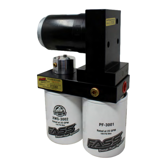
- Page 31 www.fassride.com (866) 769.3747 STEP 4: MOUNT FUEL SYSTEM Apply motor oil to gasket located on filters. Attach to system and hand tighten. Extreme Water Separator - Install XWS-3002 on side of pump with draw tube in the middle of the filter nipple. Particulate Filter –Install PF-3001 on filter nipple without the draw tube.
- Page 32 Caution: DO NOT use sealant on AN fittings A. Route suction line from the suction port from the (BHF-1002) to the ‘T’ port of the FASS pump. Cut FL-1002 to length. (measure twice cut once) Insert PL-1005 using oil. Attach to 10-301. Torque to 18 ft./ lbs.
- Page 33 E. Plug in the WH-1006-3 harness to the FASS pump and fasten with supplied zip ties. F. The FASS system is ready to be primed. Turn the key forward to the run position with out cranking the engine so that the FASS pump can begin pumping fuel. Leaving the XWS-3002 loose listen for a change of sound in the FASS motor, this will indicate the system is primed.
- Page 34 To assist with priming your FASS pump crack the XWS-3002. Put power to the FASS pump to activate the pump. When the tone of the pump changes you can tighten up the fuel filter. If you need a video of the priming process go to www.FASSride.com.
-
Page 35: Warranty
WARRANTY Disclaimer: To help insure you receive the proper system and customer support at the local level, FASS has a VIP and Authorized Dealer network representing FASS products. This is one reason you must purchase through a dealer to comply with our warranty policies. If you do not, there is no warranty! We recommend you go to www.FASSride.com, click “Find a Dealer”, put in their ZIP code, select the type of...
Need help?
Do you have a question about the TITANIUM Series and is the answer not in the manual?
Questions and answers