Table of Contents
Advertisement
Installation Guide
Split System (R-410A)
13 SEER
9,000 to 24,000 BTU/Hr
High Efficiency (13 SEER)
Single Split
Cooling only
SAFETY WARNING
Only qualified personnel should install and service the equipment. The installation, starting up, and servicing
of heating, ventilating, and air-conditioning equipment can be hazardous and requires specific knowledge and
training. Improperly installed, adjusted or altered equipment by an unqualified person could result in death or
serious injury. When working on the equipment, observe all precautions in the literature and on the tags,
stickers, and labels that are attached to the equipment.
October 2010
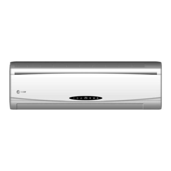
Indoor Unit
4MCW3-A
4MCW3-B
4MCW3A12
R-410A, 60Hz
Outdoor Unit
4TTK3-A
4TTK3-B
MCW-SVN15B-EN
Advertisement
Table of Contents

Related Manuals for Trane 4MCW3-A


Summary of Contents for Trane 4MCW3-A
- Page 1 High Efficiency (13 SEER) R-410A, 60Hz Single Split Indoor Unit Outdoor Unit Cooling only 4MCW3-A 4TTK3-A 4MCW3-B 4TTK3-B SAFETY WARNING Only qualified personnel should install and service the equipment. The installation, starting up, and servicing of heating, ventilating, and air-conditioning equipment can be hazardous and requires specific knowledge and training.
- Page 2 "pink" color to indicate the type of refrigerant and may contain a "dip" tube to allow for charging of liquid refrigerant into the system. For specific handling concerns with R-410A, please contact your local Trane representative. Failure to use R-410A approved service equipment could result in standard equipment exploding under R-410A higher pressure which could result in death or serious injury.
- Page 3 CFCs such as HCFCs and HFCs. Responsible Refrigerant Practices Trane believes that responsible refrigerant practices are important to the environment, our customers, and the air conditioning industry. All technicians who handle refrigerants must be certified. The Federal Clean Air Act (Section 608) sets forth the requirements for handling, reclaiming, recovering and recycling of certain refrigerants and the equipment that is used in these service procedures.
-
Page 4: Table Of Contents
Contents General Information ..........5 Accessories . -
Page 5: General Information
Warranty is based on the general terms and conditions by country. The warranty is void if the equipment is modified or repaired without the written approval of The Trane Company, if the operating limits are exceeded or if the control system or the electrical wiring is modified. -
Page 6: Accessories
Accessories Table 1. Parts list Part Name Diagram Specification Memo Mounting plate Wireless remote controller Remote controller holder Battery AAA,1.5V Tapping screw ST4.2 X 25 For mounting plate Drain hose L = 2m φ Thermal insulation 35 X 500 Drain kit Heat pump type only Drain hole cover Heat pump type only... -
Page 7: Typical Installation
Typical Installation Indoor Unit Air In Air out 1. Front panel 2. Filter 3. Guide Louver 4. Electric plug Outdoor Unit 5. Manual Switch 6. Receiving Window 7. Bind Tape Air in 8. Remote Control 9. Connection wire 10. Drain pipe Air out 1234-TTT000-EN... -
Page 8: Installation Location
Installation location Indoor Unit WARNING Adequate Support! Wall structure must be adequate to support the weight of the unit. Failure to ensure adequate structural support could result in unit falling from its location which could result in death, serious injury, or equipement or property-only damage. The air inlet and outlet should be far away from anything that could prevent the air from reaching all parts of the room. -
Page 9: Installation
Installation Indoor Unit Installation WARNING Hazardous Service Procedures! The maintenance and troubleshooting procedures recommended in this section of the manual could result in exposure to electrical, mechanical or other potential safety hazards. Always refer to the safety warnings provided throughout this manual concerning these procedures. -
Page 10: Installing The Water Drain Pipe
Insert a sleeve into the hole to prevent the connection piping and wiring from being damaged when passing through the hole. NOTICE When a wall sleeve is not used, it is then necessary to drill a straight hole in the wall. If the hole is not straight and uniform, this could result in water leaking from condensation, resulting in property damage. -
Page 11: Installing The Connection Pipe
Take out the piping from body case, wrap the piping electric wire, water pipe with tape and put them through the piping hole. Hang the mounting slots of the indoor unit on the upper tabs of the rear panel and check if it is firm enough. -
Page 12: Connect Indoor And Outdoor Electric Wires
Connect indoor and outdoor electric wires WARNING Hazardous Voltage! Disconnect all electric power, including remote disconnects before servicing. Follow proper lockout/tagout procedures to ensure the power can not be inadvertently energized. Failure to disconnect power before servicing could result in death or serious injury. -
Page 13: Outdoor Condensation Drainage (Heat Pump Type Only)
After finishing evacuation, shut Low handle of manifold valve to stop the vacuum pump. (Keep evacuating for more than 15 minutes and make sure the reading of multi-meter is - 1.0x10 pa (-76cmHg) Fully open high/low pressure valves. Remove charging hose from charging end of low pressure valve. Tighten bonnet of low-pressure valve. -
Page 14: Check After Installation And Test Operation
Check after Installation and Test Operation Items to check Possible problems they generate Has the unit been attached firmly? The unit may drop, shake or emit noise. It may cause insufficient cooling(heating) Have you done the refrigerant leakage test? capacity. Is heat insulation sufficient? It may cause condensation and dripping. -
Page 15: Connection Pipe
Connection Pipe 4MCW3509A1AA 4MCW3512A1AA 4MCW3518B1AA 4MCW3524B1AA 4TTK3509A1AA 4TTK3512A1AA 4TTK3518B1AA 4TTK3524B1AA 13 SEER (60 Hz) Refrigerant Charge (lbs) 2.2 (R-410A) 2.3 (R-410A) 4.84 (R-410A) 5.07 (R-410A) Length (m) Gas additional charge (g/m) Connection Liquid Pipe (mm) 6 (1/4") 6 (1/4") 9.52 (3/8") 9.52 (3/8") Outer Pipe... -
Page 16: Wiring Diagrams
Wiring Diagrams WARNING Hazardous Voltage! Disconnect all electric power, including remote disconnects before servicing. Follow proper lockout/tagout procedures to ensure the power can not be inadvertently energized. Failure to disconnect power before servicing could result in death or serious injury. Indoor Units Figure 1. -
Page 17: Outdoor Units
Figure 2. 4MCW3518 & 4MCW3524 Outdoor Units Figure 3. 4TTK3509 1234-TTT000-EN... - Page 18 Figure 4. 4TTK3512 Figure 5. 4TTK3518 1234-TTT000-EN...
- Page 19 Figure 6. 4TTK3524 1234-TTT000-EN...
- Page 20 HVAC systems, comprehensive building services, and parts. For more information, visit www.Trane.com. Trane has a policy of continuous product and product data improvement and reserves the right to change design and specifications without notice. © 2010 Trane All rights reserved...
Need help?
Do you have a question about the 4MCW3-A and is the answer not in the manual?
Questions and answers