Veeder-Root HydrX Installation Manual
Fuel conditioning system
Hide thumbs
Also See for HydrX:
- Setup & operation manual (35 pages) ,
- Quick help (11 pages) ,
- Manual (4 pages)

Related Manuals for Veeder-Root HydrX


Summary of Contents for Veeder-Root HydrX
- Page 1 Manual No: 577014-446 • Revision: E ™ HydrX Fuel Conditioning System Installation Manual...
- Page 2 Customer Service will work with production facility to have the replacement product shipped as soon as possible. If “lost” equipment is delivered at a later date and is not needed, Veeder-Root will allow a Return to Stock without a restocking fee.
-
Page 3: Table Of Contents
Installing FC Into Sump ..................15 STP Adapter Assembly Installation - The Red Jacket STP........16 STP Adapter Assembly Installation - FE Petro STP..........17 Attaching Hoses Between HydrX System In-Sump Components ......18 FCC Installation ......................21 HydrX System Wiring Fuel Conditioner Inlet/Outlet Valve AC Power Connections ...........22 Fuel Conditioner Intrinsically-Safe Wiring Connections ..........22... - Page 4 ........30 Figure 32. TLS-450PLUS Access ................32 Figure 33. FC Mag Probe/Pressure Sensor Connection to TLS-450PLUS ...32 Figure 34. RS-232 Connections FCC to TLS-450PLUS ........33 Tables Table 1. HydrX System Parts List ................4 Table 2. HydrX System Spare Parts List ..............34...
-
Page 5: Overview
Introduction Overview The HydrX™ Fuel Conditioning System is installed and used in diesel STP containment sumps. Its purpose is to remove accumulated water from the tank bottom and help prevent microbial growth that can lead to broad fueling system contamination and, ultimately, corrosion of fueling system components. -
Page 6: Fuel Conditioner (Fc) Assembly
Introduction Overview Figure 2. HydrX In-Sump Components Fuel Conditioner (FC) Assembly The Fuel Conditioner (FC) Assembly connects to the STP and to the Water Intake Device (WID) at the top of the WID Riser. The FC returns processed fuel to the tank through a port in the Guide Tube flange. Components of the FC are shown in Figure 3. -
Page 7: Fuel Conditioning Controller (Fcc)
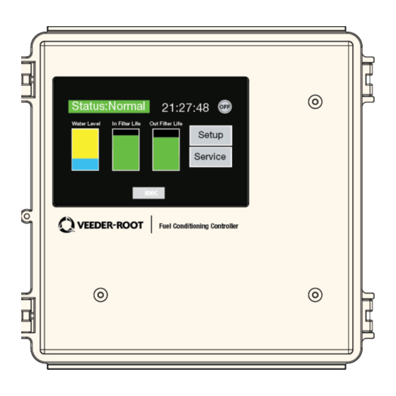
Fuel Conditioning Controller (FCC) The HydrX system is controlled by the FCC which is mounted on a wall in the back office (see Figure 4). The FCC monitors the Fuel Conditioner in the sump. The FCC turns the pump on via the pump request wire from the FCC to the Pump Relay box. -
Page 8: Contractor Certification Requirements
Introduction Contractor Certification Requirements Contractor Certification Requirements Veeder-Root requires the following minimum training certifications for contractors who will install and setup the equipment discussed in this manual: Service Technician Certification (Previously known as Level 2/3): Contractors holding valid Technician Certifications are approved to perform installation checkout, startup, programming and operations training, system tests, troubleshooting and servicing for all Veeder-Root Series Tank Monitoring Systems, including Line Leak Detection. -
Page 9: Safety Precautions
Introduction Safety Precautions Safety Precautions The following safety symbols are used throughout this manual to alert you to important safety hazards and precautions. EXPLOSIVE FLAMMABLE Fuels and their vapors are extremely explosive if Fuels and their vapors are extremely flammable. ignited. -
Page 10: Warnings And Instructions
2. If an E-stop is required by national or local codes or a local authority having jurisdiction, the HydrX Fuel Conditioning Controller (FCC) power must be supplied by a 15 amp circuit that can be interrupted by the same E-Stop as the FCC pump. -
Page 11: Requirements For Use
• The selection of any Veeder-Root product must be based upon physical specifications and limitations and the product’s compatibility with the materials to be handled. Veeder-Root makes no warranty of fitness for a particular purpose. -
Page 12: Operating Precautions
1000 feet. Wire runs must be less than 1000 feet to meet intrinsic safety requirements. Splices Veeder-Root recommends that no splices be made in the wire run between a sensor or probe junction box and the console. Each splice degrades signal strength and could result in poor system performance. ... -
Page 13: Sensor And Probe Junction Boxes
The interior volume of each junction box must be a minimum of 16 cubic inches. Veeder-Root recommends the following junction boxes or equivalent: • Appleton Electric Co. - JBDX junction box, JBK-B cover, and JB-GK-V gasket. -
Page 14: Installation
HydrX Site Inspection Guide. 2. Figure 6 shows the preferred location for the WID Riser. Refer to your HydrX Site Inspection Guide to determine the tank tilt. Since the Guide Tube directs the deployment of the Water Intake Device (WID), it must be pointed in the direction of the pooling water. -
Page 15: Figure 6. Guide Tube Installation Example - Tank Tilting Away From Manway
Installation WID Riser and Guide Tube Installation Figure 6. Guide Tube Installation Example - Tank Tilting Away From Manway... -
Page 16: Figure 7. Guide Tube Installation Example - Tank Tilting Toward
Installation WID Riser and Guide Tube Installation Figure 7. Guide Tube Installation Example - Tank Tilting Toward Short End of The Tank... -
Page 17: Water Intake Device Installation
1. Get the Water Intake Device (WID) assembly from the kit. The WID length and tube configuration was determined by measurements made in the HydrX Site Inspection Guide. 2. At the Guide Tube flange uncoil the WID tubing assembly while pushing the tube’s metal rectangular end down into the Guide Tube flange (see Figure 8). -
Page 18: Fuel Conditioner (Fc) Installation
Installation Fuel Conditioner (FC) Installation Fuel Conditioner (FC) Installation Attaching FC Valve Wiring Conduit Prior to lowering the Fuel Conditioner into the sump it is recommended that the electrical conduit components for the FC inlet/outlet valves be installed as shown in Figure 10. V-R Conduit Kit (P/N 330020-885) contains all of the necessary parts shown in the figure. -
Page 19: Installing Fc Into Sump
1. The dimensions of the FC are shown in Figure 12 and will require a minimum of 37 inches of vertical clearance (from manway to sump cover). This clearance must be confirmed when the HydrX site inspection is conducted prior to ordering the equipment. -
Page 20: Stp Adapter Assembly Installation - The Red Jacket Stp
Installation Fuel Conditioner (FC) Installation STP Adapter Assembly Installation - The Red Jacket STP Turn off the electricity, tag and lockout the electrical power switch to the dispenser/pump. Relieve pump pressure before proceeding with this installation. 1. Get the STP Adapter Assembly from the kit. 2. -
Page 21: Stp Adapter Assembly Installation - Fe Petro Stp
Installation Fuel Conditioner (FC) Installation STP Adapter Assembly Installation - FE Petro STP Turn off the electricity, tag and lockout the electrical power switch to the dispenser/pump. Relieve pump pressure before proceeding with this installation. 4. Get the STP Adapter Assembly from the kit (see Figure 15. Figure 15. -
Page 22: Attaching Hoses Between Hydrx System In-Sump Components
Installation Fuel Conditioner (FC) Installation Attaching Hoses Between HydrX System In-Sump Components Figure 17 shows a FC manifold hose connection mock-up and Figure 18 is an example installation. Figure 17. FC Hose Connection Mock-Up Figure 18. FC Hose Connection Installed... -
Page 23: Figure 19. Fc Manifold Hose Connections
Installation Fuel Conditioner (FC) Installation 1. Get the three braided corrugated metal hoses from the kit: •The STP Adapter Assembly to FC manifold ‘P’ fitting hose with 1/2” JIC elbow female fitting one end and 1/ 2” JIC straight female fitting other end. •The FC manifold ‘T’... -
Page 24: Figure 20. Wid Hose Connections
Installation Fuel Conditioner (FC) Installation Figure 20. WID Hose Connections 5. Place the flaretite seal from the kit onto the 3/8” JIC male end of the tank return adapter fitting. Attach the 3/8” JIC elbow female fitting end of the hose to the 3/8” JIC male drain adapter fitting. Attach the 1/2” JIC straight end of the hose to the fitting marked ‘T’... -
Page 25: Fcc Installation
Fuel Conditioner (FC) Installation FCC Installation Control of the HydrX system is maintained by the FCC which is mounted in the back office (see Figure 21). Figure 21. FCC Dimensions The FCC is to be mounted to the wall in a dry, non-hazardous location such as the back office of the station. Get the FCC mounting bracket hardware from the kit. -
Page 26: Hydrx System Wiring
HydrX System Wiring Disconnect, tag and lock out power at the power panel when making AC wiring connections. Fuel Conditioner Inlet/Outlet Valve AC Power Connections 1. Pull two pairs #14 THHN and 1one #14 THHN ground, one marked Inlet Valve and one marked Outlet Valve, from the FCC into the STP power junction box. -
Page 27: Figure 24. Epoxy Sealing Fc Mag Probe And Fc Pressure Sensor
HydrX System Wiring Fuel Conditioner Intrinsically-Safe Wiring Connections Figure 24. Epoxy Sealing FC Mag Probe and FC Pressure Sensor Field Connections... -
Page 28: Fe Petro Pump Controller Dip Switch Setting
FE Petro Pump Controller DIP Switch Setting When an FE Petro pump is used with the HydrX system, the Controller’s Extended Run Disable DIP switch must be set to the On position (disabled). The location of this DIP switch is shown in two FE Petro Controllers (see Figure 25). -
Page 29: Fcc & Fc Power Wiring Connections To Tls-450Plus
WARNING NOTICE If an E-stop is required by national or local codes or a local authority having jurisdiction, the HydrX • AC line on the FCC box, I/O module, Fuel Conditioning Controller (FCC) power must be supplied by a 15 amp circuit that can be hook isolation box and dispenser inputs all need to interrupted by the same E-Stop as the FCC pump. -
Page 30: Figure 27. Wiring Using An Fe Petro Dhi Box
WARNING NOTICE If an E-stop is required by national or local codes or a local authority having jurisdiction, the HydrX • AC line on the FCC box, I/O module, Fuel Conditioning Controller (FCC) power must be supplied by a 15 amp circuit that can be hook isolation box and dispenser inputs all need to interrupted by the same E-Stop as the FCC pump. -
Page 31: Figure 28. Wiring Using An Cpi Isolation Board
WARNING NOTICE If an E-stop is required by national or local codes or a local authority having jurisdiction, the HydrX • AC line on the FCC box, I/O module, Fuel Conditioning Controller (FCC) power must be supplied by a 15 amp circuit that can be hook isolation box and dispenser inputs all need to interrupted by the same E-Stop as the FCC pump. -
Page 32: Figure 29. Converting A Tls-350 To A Tls-450Plus
Secondary relay must be maintained if present. If not present power panel before before insatllation of Hydrx it does not need to be added wiring the pump. • All conductors #14 THHN • Make ground connection in accordance with local codes. -
Page 33: Figure 30. Adding Red Jacket Isotrol To A Pre Wired Control Panel
If an E-stop is required by national or local codes or a local authority having jurisdiction, the HydrX • Diesel line leak terminal shown as “3A and 3”, Fuel Conditioning Controller (FCC) power must be supplied by a 15 amp circuit that can be number may vary. -
Page 34: Figure 31. Adding Fe Dhi To A Pre-Wired Control Panel
If an E-stop is required by national or local codes or a local authority having jurisdiction, the HydrX Fuel Conditioning Controller (FCC) power must be supplied by a 15 amp circuit that can be •... -
Page 35: Fc Probe/Pressure Sensor Wiring To Tls-450Plus
HydrX System Wiring FC Probe/Pressure Sensor Wiring to TLS-450PLUS FC Probe/Pressure Sensor Wiring to TLS-450PLUS WARNING FAILURE TO COMPLY WITH THE FOLLOWING WARNINGS AND SAFETY PRECAUTIONS COULD CAUSE DAMAGE TO PROPERTY, ENVIRONMENT, RESULTING IN SERIOUS INJURY OR DEATH. The equipment is used in location where lethal voltages and explosive vapors or flammable fuels may be present. -
Page 36: Figure 32. Tls-450Plus Access
HydrX System Wiring FC Probe/Pressure Sensor Wiring to TLS-450PLUS Figure 32. TLS-450PLUS Access 1. Refer to Figure 33 below for TLS-450PLUS FC Mag Probe and FC Pressure Sensor wiring connections. Figure 33. FC Mag Probe/Pressure Sensor Connection to TLS-450PLUS... -
Page 37: Fcc Rs-232 Serial Communication Wiring To Tls-450Plus
FCC RS-232 Serial Communication Wiring To TLS-450Plus Figure 34 diagrams the RS-232 serial comm connection between the FCC and the TLS-450PLUS. Figure 34. RS-232 Connections FCC to TLS-450PLUS... -
Page 38: Spare Parts Lists
Spare Parts Lists FCC RS-232 Serial Communication Wiring To TLS-450Plus Spare Parts Lists Table 2. HydrX System Spare Parts List Part Number Description Category 330020-878 KIT - Hose -pressure Port to Manifold Replacement 330020-876 Kit - Hose - Tank Return...
Need help?
Do you have a question about the HydrX and is the answer not in the manual?
Questions and answers