Veeder-Root HydrX Setup & Operation Manual
Fuel conditioning controller
Hide thumbs
Also See for HydrX:
- Installation manual (39 pages) ,
- Quick help (11 pages) ,
- Manual (4 pages)

Related Manuals for Veeder-Root HydrX


Summary of Contents for Veeder-Root HydrX
- Page 1 Manual No: 577014-466 Revision: B HydrX Fuel Conditioning Controller ™ Setup & Operation Manual...
- Page 2 Customer Service will work with production facility to have the replacement product shipped as soon as possible. If “lost” equipment is delivered at a later date and is not needed, Veeder-Root will allow a Return to Stock without a restocking fee.
-
Page 3: Table Of Contents
Fault Diagnostic Two Screen ..................14 ATG Sensor Data ......................14 FCC Software Upgrade ....................15 FCC Clock Setup ......................16 TLS-450PLUS Setup Install HydrX Fuel Conditioning System Software ............18 FC Mag Probe Setup ......................19 FC Pressure Sensor Setup .....................20 External Input Setups .....................20 FCC Switch Contact Setup..................20 Diesel Pump Switch Hook SetuP ................21... - Page 4 Table of Contents Figures Figure 1. HydrX Fuel Conditioning Controller Front Display ........2 Figure 2. FCC Display Home Screen ..............2 Figure 3. Auto Run Time Screen ................3 Figure 4. Data Entry ....................3 Figure 5. Data Entry Keypad Popup ..............4 Figure 6.
-
Page 5: Overview
Intelligent pump control continuously monitors the HydrX system and determines the best strategy for water removal while managing the STP to minimize run time while providing the required time to remove water and clean fuel in the UST. In addition, the intelligent pump control prioritizes line and tank testing to maintain site compliance. -
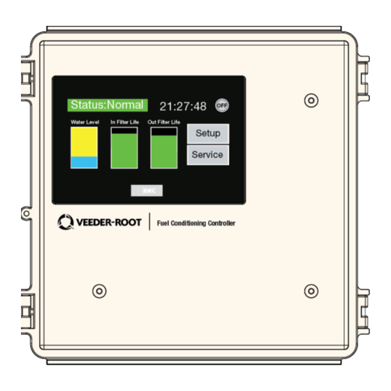
Page 6: Figure 1. Hydrx Fuel Conditioning Controller Front Display
UIOM relays (see Figure 1). This setup manual assumes the FCC is installed and wired both to the TLS-450PLUS and the HydrX Fuel Conditioner according to the instructions in the HydrX Installation Manual 577014-446. -
Page 7: Fcc Setup
Auto Run Time Overview Auto Run Time is a user adjustable setting that tells the FCC which hours the HydrX can run the STP and is typically programmed for quiet hours or overnight shutdowns when sales are slow, or a site is closed for business. -
Page 8: Cycle Time Parameters Overview
The Cycle Time and Conditioner Processing Cycle parameters described below include typical, recommended or required settings. These parameters should initially be set as outlined below and modified only after observing site operations and the HydrX systems water loading behavior and fuel quality. While highly configurable for any unique site conditions or operating requirements, the values below will provide acceptable performance in most circumstances while balancing STP running hours. -
Page 9: Conditioner Tank Settings Screen
HydrX Fuel Conditioner (FC) tank. This setting should be limited to 30 seconds, maximum, to prevent any possibility of spilling fuel or ejecting excessive amounts of fuel into the waste water. -
Page 10: Conditioner Processing Cycles Overview
4. Sweep Cycles - limits the number sweeps intended to move any standing water along the tank bottom to the lowest point. Sweeping improves the overall water collection efficiency of the HydrX FC by encouraging water to move to the end vacuum point that is optimized for water extraction as well as keeping the lines clear from debris buildup in the WID. -
Page 11: Filter End Of Life (Eol) Overview
HydrX vacuum element. 4. Inlet End of Life - is the percentage value of remaining filter life that the HydrX will signal the user that the inlet filter must be replaced. This is typically set to 5% to prevent any possibility of contamination or system degradation caused by completely clogged filter elements. -
Page 12: Atg Device Mapping Overview
ATG Device Mapping Overview ATG Device Mapping Tells the HydrX FCC about the physical locations of the devices within the TLS ATG. As probes, sensors and the Fuel Conditioner, they are assigned physical locations, like probe 1, probe 2, LPR 1, LPR 2, Fuel Conditioner 1, etc. -
Page 13: Service
Outlet filter pressure is measured during the vacuum interval under a vacuum created by an integral venturi element in the HydrX Fuel Conditioner (FC) manifold. As the filters accumulate debris and clog, the pressure changes from this reference value, the pressure difference indicating remaining filter life. -
Page 14: Auto Cycle Button
HydrX Fuel Conditioner (FC) float is on the bottom of the FC tank. The Water Cycles setting is the number of consecutive vacuum cycles without water removal when the HydrX Fuel Conditioner (FC) float is not on the bottom of the FC tank. -
Page 15: Filter Performance Screen
The Filter Performance screen displays the read-only FC inlet and outlet valve status (see Figure 12). ‘P0’ is the pressure measured by the HydrX FCC when a filter is new or has been replaced. ‘P’ is the current pressure as measured by the HydrX FCC that indicates if the filter is clogging which diminishes filter life. -
Page 16: Service Counter Screen
Service Service Counter Screen • Current and Last Month accumulation, Current and Last Year accumulation (see Figure 14). Figure 14. Water Collection (Month/Year) Screen Monitoring patterns in these distributions can help users identify if water is collected in gradual condensing type conditions, dropped with deliveries, i.e., correlating daily accumulations to ATG deliveries or ingress after wet weather periods in either daily or monthly accumulations. -
Page 17: Fc Comm Diagnostic Screen
Service FC Comm Diagnostic Screen FC Comm Diagnostic Screen The FCC displays read-only communications diagnostic counters of serial communications between the FCC and ATG Fuel Conditioner (FC) functions (see Figure 17). Figure 17. FC Pressure Sensor Diagnostic Screen FC Probe Comm Diagnostic Screen The FCC displays read-only diagnostics counters of serial communication with the FC Mag Probe (see Figure 18). -
Page 18: Fault Diagnostic Two Screen
Touch the Home button to return to the FCC Home screen (see Figure 2). ATG Sensor Data Touch the ATG Data button to display read-only HydrX parameters from the Fuel Conditioner Mag Probe and pressure sensor readings that are sent from the TLS-450PLUS (see Figure 21). Touch the Home button to return to the FCC Home screen (see Figure 2). -
Page 19: Fcc Software Upgrade
Service FCC Software Upgrade FCC Software Upgrade To avoid electric shock do not touch any wiring terminals inside the FCC while performing this procedure. 1. If you have a FCC upgrade thumb drive with the software upgrade already on it, go to Step 3. 2. -
Page 20: Fcc Clock Setup
Service FCC Clock Setup FCC Clock Setup To set the FCC internal clock on initial startup follow the steps below. 1. Touch the upper left corner of the FCC display status bar and press it until the Maintenance screen appears (see Figure 24). -
Page 21: Figure 27. Tls-450Plus Usb Ports
Service FCC Clock Setup 4. On the Main Menu page touch the Clock Setting button open the Clock Set page (see Figure 27) Figure 27. Main Menu Page 5. On the Clock Set page, observe the button functions in Figure 28 to reset the date and time. Touch the number buttons to enter date/time. -
Page 22: Tls-450Plus Setup
TLS-450PLUS Setup Install HydrX Fuel Conditioning System Software The TLS-450PLUS ATG must have Version 9R or later system software and have the HydrX System ‘In-Sump Fuel Conditioner’ software feature installed. If necessary, install the In-Sump Fuel Conditioner software feature as described below. -
Page 23: Fc Mag Probe Setup
TLS-450PLUS Setup FC Mag Probe Setup IMPORTANT! During feature activation, which only takes a few minutes, there must be no dispensing. 4. During the installation, the current status of the feature will be indicated by the following messages: •Ready to Activate •Activation in Progress 5. -
Page 24: Fc Pressure Sensor Setup
TLS-450PLUS Setup FC Pressure Sensor Setup FC Pressure Sensor Setup 1. Open the Setup Devices Index and touch the Line Pressure Sensor button to open the Line Pressure Sensor setup screen. Figure 32. Accessing TLS-450PLUS Line Pressure Sensor Setup Screen 2. -
Page 25: Diesel Pump Switch Hook Setup
5. Touch Label field and enter a description of this relay (up to 20 alphanumeric characters) that will appear on the console screens and in reports, e.g., ‘HydrX Service’. 6. Touch the Type field and select ‘Standard’ (On/Off state is determined by assigned alarms or warnings). -
Page 26: Relay Setup (Output Relay That Will Engage The Stp)
TLS-450PLUS Setup Relay Setup (Output Relay that will engage the STP) Relay Setup (Output Relay that will engage the STP) 1. Go to the screen, open the Setup Devices Index and touch the Relay button to Menu>Setup>Devices open the Relay setup screen. Figure 34. -
Page 27: Pumps And Lines Setup
TLS-450PLUS Setup Pumps and Lines Setup Pumps and Lines Setup Pump Setup 1. Go to Lines, open the Setup Devices Index and touch the Pumps button to open Menu>Setup>Pump and Pump setup screen. Figure 35. Pumps Setup Screen 2. Touch the lower left hand corner where it shows Pump 1 and select the Pump along the bottom horizontal section of the screen for the Pump you want to configure. -
Page 28: Line Setup
TLS-450PLUS Setup Pumps and Lines Setup Line Setup The Lines setup may differ depending if the site is running DPLLD or not. Both sets of instructions will be shown below: 1. Go to Menu>Setup>Pump and Lines, open the Setup Devices Index and touch the Line button to open the Line setup screen. -
Page 29: Custom Alarms Setup
Fuel Conditioner. Figure 38. Custom Alarms Setup Screen Example 2. Touch the Device Number field and select the specific device, e.g., ‘External Input X : HydrX Service’ . 3. Touch the Alarm field and select ‘External Input Alarm’. -
Page 30: Fuel Conditioner Setup
2. Touch the Enabled radio button to configure this Fuel Conditioner. 3. Touch the Label field to enter a name for this device, e.g. ‘HydrX 1’ . 4. Touch the Conditioner Probe field to assign the mag probe in this Fuel Conditioner. -
Page 31: Operation
Operation Operation and service of the HydrX system is controlled from the FCC front panel following the instructions discussed in this manual. The TLS-450PLUS HydrX overview screen allows the user to view the current status of the HydrX system only. - Page 32 Check drain valve seated Status: Pressure User programmed custom Check filters Insufficient STP pressure Fault alarm, i.e., "HydrX Service" Check STP pressure at HydrX adapter port Check drain valve seated User programmed custom Check filter cover o-rings Status: Vacuum Fault Insufficient STP vacuum alarm, i.e., "HydrX Service"...
-
Page 33: Hydrx System Specifations And Default Settings
HydrX System Specifations and Default Settings Specifications Attribute Rating Unit Comment Filtration Multi-Stage Filtration Inlet Type: Particle plus Coalescing media Outlet Type: Fine water separation Filtration: 25 micron (all elements) End of life (EOL) Inlet filter pressure drop: End of life (EOL) Outlet filter pressure drop:... -
Page 34: Recommended Hydrx Fuel Conditioning Controller Settings
HydrX System Specifations and Default Settings Recommended HydrX Fuel Conditioning Controller Settings Recommended HydrX Fuel Conditioning Controller Settings Category Setting Unit Comment Auto Run Time Start 00:00 HH:MM 24 hour format 08:00 HH:MM 24 hour format Cycle Time Parameters Fill Time...
Need help?
Do you have a question about the HydrX and is the answer not in the manual?
Questions and answers