
Related Manuals for Dinolift DINO 280RXT


Summary of Contents for Dinolift DINO 280RXT
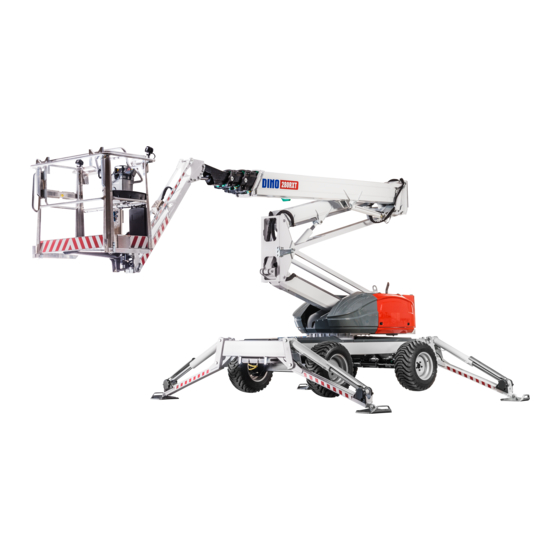
- Page 1 OPERATING INSTRUCTIONS DINO 280RXT Manufacturer: Dinolift Oy Raikkolantie 145 | FI-32210 LOIMAA Tel. + 358 20 1772 400 | info@dinolift.com | www.dinolift.com...
- Page 2 Operating instructions • DINO 280RXT...
- Page 3 ORIGINAL OPERATING INSTRUCTIONS Valid from serial number: 280RXT 80001 --> SERIAL NUM. CHANGE DATE Auto levelling change 24.5.2018...
-
Page 4: Table Of Contents
Operating instructions • DINO 280RXT TABLE OF CONTENTS TO THE OPERATOR ....................7 1.1. OVERVIEW OF THE UNIT .................. 8 1.2. INTENDED USE OF THE WORK PLATFORM ........... 8 TECHNICAL SPECIFICATION ..................9 2.1. DIMENSION DRAWINGS ................. 10 2.2. REACH DIAGRAM .................... 11 2.3. - Page 5 DINO SKY RACK (OPTION) ..................57 DINO SAFE-GUARD (OPTION) ................59 FAULT FINDING ......................60 8.1. OPERABILITY OF MOVEMENTS ..............61 8.2. FAULT CODES ....................62 SERVICING AND MAINTENANCE ................64 9.1. LUBRICATION PLAN ..................66 9.2. INSPECTIONS REQUIRED BY AUTHORITIES ..........68 10.
- Page 6 Operating instructions • DINO 280RXT...
-
Page 7: To The Operator
Dinolift Oy is constantly developing its products. For this reason, the contents of this manual might not always be in full compliance with the most recent version of the product. Dinolift Oy reserves the right to modify the product without prior notice. Dinolift Oy assumes no liability WARNING for any problems caused by changed or missing data or mistakes in this manual. -
Page 8: Overview Of The Unit
Operating instructions • DINO 280RXT 1.1. OVERVIEW OF THE UNIT The unit is a wheeled, self-propelled aerial work platform. This aerial work platform complies with the standard EN280 type 1, where driving is only allowed while the boom is in transport position. -
Page 9: Technical Specification
TECHNICAL SPECIFICATION 280RXT Max. working height 28,0 m (91 ft 10") Max. platform height 26,0 m (85 ft 4") Max. outreach 16,0 m (52 ft 6") Boom rotation continuous Platform rotation 180° Jib arms 1,6m (63") / 140° Turn area refer to the reach diagram Support width 3,8 m x 4,2 m (12 ft 6"... -
Page 10: Dimension Drawings
Operating instructions • DINO 280RXT 2.1. DIMENSION DRAWINGS... -
Page 11: Reach Diagram
2.2. REACH DIAGRAM 230 kg 120 kg... -
Page 12: Example Of Machine's Nameplate
Operating instructions • DINO 280RXT 2.3. EXAMPLE OF MACHINE’S NAMEPLATE Every machine has a nameplate shown in the picture below. In the nameplate are marked the name and address of machine manufacturer, serial number of the machine and other relevant machine information. -
Page 13: Model Of Ec-Declaration Of Conformity
Raikkolantie 145 FI-32210 Loimaa, FINLAND declares that DINO 280RXT Access Platform no YGC280RXTK0080030 is in conformity with the provisions of Machinery Directive 2006/42/EC as amended and with national implementing legislation. 2006/42/EC Conformity assessment procedure followed: Annex VIII: internal control of production. -
Page 14: Model Of Inspection Protocol For The Access Platform
Operating instructions • DINO 280RXT 2.5. MODEL OF INSPECTION PROTOCOL FOR THE ACCESS PLATFORM TEST CERTIFICATE DATE: START-UP TESTS: Inspection place: Dinolift Oy Inspector's signature: BASIC INFORMATION Manufacturer: Dinolift OY Place of manufacture: Finland Raikkolantie 145 Address: 32210 LOIMAA Importer:... - Page 15 E. SAFETY AND CONTROL DEVICES F. SAFETY FEATURES 1. Safety limit switches 1. Prevention of unauthorized use 2. Sound signal 2. Locking device, covers and guards 3. Emergency descent system 3. Prevention of lifting 4. Protection of controls 4. Prevention of opening of support 5.
-
Page 16: Safety
Operating instructions • DINO 280RXT SAFETY All the essential safety instructions and warnings, relevant to transport, use and maintenance of the lift, are described in this chapter. DANGER Failure to observe these instructions and safety regulations may cause a severe injury or WARNING even death. - Page 17 TRANSFERS Observe the maximum allowed gradient when transferring the lift. During transfer in rough terrain, always try to position yourself higher than the machine. Beware of fixed or moving obstacles in the terrain or near the lift while driving. Make sure that you have a clear view of the driving path.
- Page 18 Operating instructions • DINO 280RXT LIFTING AND WORKING ON THE PLATFORM Never exceed the maximum number of persons, maximal loading or hand power, allowed for the lift. Never add load onto the platform while in the upper position. Before operating, always ensure that the safety devices and the emergency descent system are in working order.
- Page 19 OPERATING CONDITIONS The weather conditions, such as wind, visibility and rain, must always be taken into account so that these will not adversely affect the safe performance of the lifting operations. The use of the lift is prohibited, if the temperature drops under -20 °C or the wind speed exceeds 12.5 m/s Wind speed ( m/s) Conditions on land...
-
Page 20: Safety-Related Notifications
Operating instructions • DINO 280RXT 3.2. SAFETY-RELATED NOTIFICATIONS The following safety alert symbols and safety signal words are used in this manual. Observe all the safety instructions that follow these symbols, in order to avoid dangerous situations and personal injuries. - Page 21 Risk of getting crushed Risk of getting crushed Risk of getting crushed Harmful exhaust gas - moving parts - moving parts - falling objects emissions Wind speed Risk of turning over Risk of falling Support force Smoking prohibited Keep safe distance Emergency descent Fixing point for the falling guard...
-
Page 22: Safety Devices
Operating instructions • DINO 280RXT 3.3. SAFETY DEVICES 1. Supervision of transport position Transport position of the boom system is monitored with sensors: • RK3 = inductive switch for boom and arms down • RK8 = wire rope sensor for boom extention •... - Page 23 3. Chassis inclination sensor The inclination sensor RK30 monitors chassis inclination. The sensor is located under the front cover. RK30 To start the aerial operation, the chassis must be levelled with stabilisers within 1°. Inclination signal lights must be off. During aerial operation, the signal light will start flashing if the chassis inclination exceeds 1°.
- Page 24 Operating instructions • DINO 280RXT 4. Overload control of the boom The moment sensing system prevents the lift from being overloaded by limiting the outreach of the lift to the side. The allowed outreach depends on the load on the platform.
- Page 25 5. Supervision of the telescope wire ropes The telescopic boom has mechanical indicators that indicate possible failure of the wire ropes. Check the indicators with the machine in transport position, telesopic boom fully retracted. On the rear end of the boom, all four indicators must be aligned with the green areas marked with the decals.
- Page 26 Operating instructions • DINO 280RXT 6. Safety devices for hose rupture All the load-bearing cylinders are equipped with valves for rupture or leak in the hydraulic system, which prevent the load from falling. Stabiliser cylinders Lock valves 2 directions Lifting cylinder of the boom...
- Page 27 8. Emergency stop buttons Pressing down the emergency stop button shuts down the control system, stops all the movements immediately and turns off the power unit. A button can be found at each control DANGER station. When the machine is in emergency stop mode, red lights flash on all control buttons and the WARNING indicator light in the LCB center emergency stop button goes out.
-
Page 28: Basic Structure And Functions
Operating instructions • DINO 280RXT BASIC STRUCTURE AND FUNCTIONS The denominations of the machine’s essential parts and concepts, which are used later in these instructions, are described on this page. 4.1. STRUCTURE Jib cylinder Levelling cylinder of the platform (slave) -
Page 29: Basic Functions
4.2. BASIC FUNCTIONS Turning the platform Levelling the platform Lifting/lowering the boom Lifting/lowering the articulated arms Turning the boom Driving direction Note! Driving, steering and stabiliser controls reverse their operating direction according to boom rotation. -
Page 30: Operating Controls
Operating instructions • DINO 280RXT 4.3. OPERATING CONTROLS Colours used in control panels Green Boom system Blue Stabilisers Driving Yellow Emergency operation / symbol contrast colour Grey / white General Yellow symbol contrast colour is used in the symbols to highlight the movement that is activated with the control. - Page 31 Stabiliser operation and driving Direction selection for stabiliser 4-wheel steering operation Selection of stabiliser / manual 2-wheel steering operation Automatic levelling with stabilisers Crab steering Driving Steering - right Steering - left Boom operations Turning device rotation Boom Articulated arms Telescope Jib arms Turning of platform...
-
Page 32: Platform Panel Ucb
Operating instructions • DINO 280RXT 4.3.1. Platform panel UCB Emergency stop Boom operation mode Display Boom up/down Left joystick Boom rotation right/left Manual stabiliser operation mode: Driving mode Selection of stabiliser Drive forwards/backwards Boom operation mode: Steering left Articulated arms up/down... -
Page 33: Display
4.3.2. Display The basic display view after start-up shows the status of the stabilisers and the inclination of the chassis. Stabiliser display: Aerial display LIMITER: LIMITER: XXXXXOOOOO XXXXXOOOOO FUEL LEVEL FUEL LEVEL AERIAL: AERIAL: STAB: (OOOO) STAB: (OOOO) RUN TIME: 80:00 RUN TIME: 80:00... - Page 34 Operating instructions • DINO 280RXT Press enter to move to selection of other display views. Alternate display views can be browsed with arrow keys. Notice! Information shown on the displays varies depending on machine configuration! Operating time display Information Values...
- Page 35 Sensor display 1 Information Values Description Working envelope pressure limit percentage value Working envelope length limit percentage value Actual differential pressure on lifting cylinder ° Actual main boom angle Actual length of telescopic boom Actual load on platform STAB ON/OFF Operation of stabilisers allowed / prevented AERIAL ON/OFF...
-
Page 36: Chassis Control Panel Lcb
Operating instructions • DINO 280RXT 4.3.3. Chassis control panel LCB Selector key switch Emergency stop with indicator light Warning light LCB controls active Activation UCB controls active Limited operating mode for shortened transport / storage configuration. -
Page 37: Operation
DANGER WARNING OPERATION CAUTION 5.1. START-UP NOTICE All the regular servicing measures must be carried out before using the lift. The operator must do a worksite inspection and daily maintenance: • at the beginning of each workday • before operating the lift at a new worksite •... - Page 38 Operating instructions • DINO 280RXT 2. Documents • Are the Operation and Service Instructions for this lift present? • Are inspections and servicing carried out in accordance with the instructions and have the defects affecting the safety been checked as repaired? (Inspection protocols) 3.
-
Page 39: Instructions For Working
5.2. INSTRUCTIONS FOR WORKING COMBUSTION ENGINE Starting the combustion engine 1. Select the control position UCB or LCB with the key switch. 2. Activate control system with activation pedal (UCB) or activation button (LCB) 3. Press the “glowing” button, if necessary. •... - Page 40 Operating instructions • DINO 280RXT ELECTRIC MOTOR Connect the plug to the power supply. Starting the electric motor from the platform. 1. Turn the key switch to position UCB. 2. Activate control system with activation pedal. 3. The electric motor starts automatically once any of the movements is activated.
-
Page 41: Driving
5.2.1. Driving The lift is driven from UCB centre. Notice, that the electric motor can not be used while driving. DANGER Check the terrain before driving! Do not drive in dangerous conditions. Risk of WARNING overturning! The inclination must not exceed 25 while driving! Be careful that the platform does not hit the ground while driving on uneven terrain. - Page 42 Operating instructions • DINO 280RXT 4. Select the steering mode. 3 different steering modes can be selected. The selected steering mode is shown with the signal lights on the buttons. 2-wheel steering. Only the foremost wheels turn. 4-wheel steering. Only available in slow driving speed range.
-
Page 43: Support Position
5.2.2. Support position The stabilizers can only be operated, while the articulated arms and boom are on the support and the telescopic boom is fully retracted. 1. Attach the safety harness to the anchor point on the platform. 2. Activate controls with activation pedal. None of the movements may be activated. - Page 44 Operating instructions • DINO 280RXT To adjust the stabilisers individually: 5. Select direction of movement with selection buttons. A signal light on the button will indicate that the function is active. The function will deactivate: • when the button is pressed again, •...
- Page 45 Before operating the lift, check that: • the chassis is level • that the wheels are off the ground DANGER • that all the stabilisers are well supported on the ground WARNING Carry out all daily maintenance routines and inspections in accordance with the CAUTION maintenance instructions before operating the lift.
-
Page 46: Operating The Boom From The Platform
Operating instructions • DINO 280RXT 5.2.3. Operating the boom from the platform The operation of the boom is only possible if the stabilisers are firmly supported on the ground and the chassis is levelled. DANGER Risk of falling! Wear a safety harness while on the platform, and WARNING fix it to the point marked for them. - Page 47 DANGER Risk of overturning! Do not overload the machine. WARNING It is strictly prohibited to take additional load in the upper position. 55 kg 110kg 90 kg Do not exceed the allowed manual force (400N), or load the platform more 230 kg MAX 215 KG MAX 350KG...
-
Page 48: Operating The Boom From The Chassis Panel
Operating instructions • DINO 280RXT 6. Lowering the platform to transport position Before lowering the boom onto the transport support, retract the telescope completely and turn the platform perpendicular to the boom. 7. When leaving the lift • switch off the power unit •... -
Page 49: Measures To Be Taken At The End Of The Working Day
5.2.5. Measures to be taken at the end of the working day At the end of a workday: 1. Retract the telescope completely. 2. Check that the platform is perpendicular to the boom. 3. Lower the boom onto the support. The limit switch on the transport support prevents operation of the stabilisers if the platform is not down 4. -
Page 50: In Case Of Emergency
Operating instructions • DINO 280RXT 5.3. IN CASE OF EMERGENCY 5.3.1. When at risk of losing stability Reduced stability can be caused by a fault in the lift, the wind or other lateral force, collapse of the standing base or negligence in providing sufficient support. In most cases one sign of reduced stability is the inclination of the lift. -
Page 51: In Case The Emergency Descent Battery Is Empty
The emergency descent system can also be used for raising the stabilisers to the transport position: • Start the emergency descent unit from the UCB control panel • Lift the stabilisers Setup of the system • battery 12V 68Ah • hydraulic unit 12 VDC •... -
Page 52: In Case Of Malfunctioning Control System
Operating instructions • DINO 280RXT 5.3.4. In case of malfunctioning control system In case of problems with the moment sensing system or control valve: 1. Try to find out the reason for the problem and try restarting the machine. 2. Reduce the outreach to the side by retracting the telescopic boom fully using the emergency retraction system. - Page 53 DANGER Risk of turning over the lift and serious structural damage! Manual operation of the WARNING valves overrides critical safety devices and the emergency stop system. The system should only be used to rescue a trapped operator in an emergency in case normal control system is not operational.
-
Page 54: Long-Term Storage
Operating instructions • DINO 280RXT 5.4. LONG-TERM STORAGE Clean the machine carefully. Lubricate and apply protective grease to it before putting it into storage for a longer period of time. Repeat the cleaning and lubrication procedures before putting the lift back in operation. -
Page 55: Lifting
L ~ 4000 mm x 2 L ~ 2650 mm x 1 5.5.2. Lifting The device can be lifted from the lugs shown in the picture. Lugs are placed symmetrically on both sides of the device. Lifting lugs are also marked in the machine with instructional labels. -
Page 56: Shortened Transport Position
Operating instructions • DINO 280RXT 5.5.3. Shortened transport position Transport length of the machine can be reduced by turning the jib arms and the platform underneath the telescopic boom. While the machine is in the shortened transport position, all other movements, including driving, are disabled. -
Page 57: Dino Sky Rack (Option)
DINO SKY RACK (OPTION) Dino Sky Rack is a DINO accessory intended for lifting of panels of sheet material and pipes. Technical specifications 160 XT/XTB , 180XT/XTB , 210XT/XTB 280RXT Max number of persons on platform Max. allowed load on rack 100 kg Max. - Page 58 Operating instructions • DINO 280RXT MAX. 500 KG DANGER Tip over hazard! WARNING The panels will increase the area exposed to wind and decrase the stability of the machine. Follow all instructions on maximum panel size P / D and operating conditions.
-
Page 59: Dino Safe-Guard (Option)
DINO SAFE-GUARD (OPTION) Upper control centre can be equipped with a safe-guard. The device helps to protect the user from entrapment and crushing hazards while driving or working near obstructions. The safe-guard stops the machine in case the safety line over the controls is pushed so that the magnet at the end of the line is released from the socket. -
Page 60: Fault Finding
Operating instructions • DINO 280RXT FAULT FINDING FAULT REMEDY 1. The engine does not start Switch on the main switch and activate the system The main current is not connected. by depressing the pedal switch (UCB) or by pressing the activation button (LCB). -
Page 61: Operability Of Movements
8.1. OPERABILITY OF MOVEMENTS RK11 Stabilisers up OFF OFF OFF OFF OFF OFF OFF OFF OFF RK11 Stabilisers down DISP Boom rotation center RK1, OFF OFF position, telescope in RK1, Boom rotation turned OFF OFF OFF OFF Telescope out OFF OFF OFF OFF Boom + Articulated OFF OFF... -
Page 62: Fault Codes
Operating instructions • DINO 280RXT Optional warning signals: Warning for boom lowering movements (option). • Works while driving boom movements (marked with in the table) from the UCB controls. • Warning buzzer sounds on ground level to warn pedestrians in the area. - Page 63 NOTES...
-
Page 64: Servicing And Maintenance
Maintenance instructions • DINO 220RXT SERVICING AND MAINTENANCE Maint. Schedule Person responsible Reference Daily Operator Operating instructions Competent person who is familiar with the Maintenance 1 month / 100 hours* lift instructions Competent person who is familiar with the Maintenance 6 months / 400 hours* DANGER lift... - Page 65 Maintenance item Chassis structures, boom and work platform Telescopic boom Cylinders Turning device and rotating adapter Axles and wheels Engine Hydraulic oil Hydraulic system Load holding and load regulation valves Platform levelling system Electrical system and control devices Safety devices Signs, labels and machine plates DANGER Instruction manuals...
-
Page 66: Lubrication Plan
Maintenance instructions • DINO 220RXT 2.1. LUBRICATION PLAN DINO 220-280RXT 2 + 2 4 + 4 2 x 2 280RXT... -
Page 67: Inspections Required By Authorities
2.2. INSPECTIONS REQUIRED BY AUTHORITIES Inspections must be performed in accordance with local, state or federal regulations, legislation, directives, standards. The manufacturer recommends following inspections, as required by local authorities in platforms country of origin. A pre-use inspection must be done before taking the platform to use for the first time and before first start-up after major repairs and alterations. - Page 68 Maintenance instructions • DINO 220RXT ROUTINE MAINTENANCE DURING OPERATION This chapter describes the service and maintenance operations that the operator of the platform is responsible for. Other maintenance operations require special training, tools and materials or specific measurements and adjustment values. They are separately described in maintenance instructions manual.
-
Page 69: Routine Maintenance During Operation
3.1. DAILY MAINTENANCE TASKS 3.1.1. Chassis, boom and work platform Check the overall condition of access systems, work platform, gate and handrails. Check that the chassis, stabilisers and boom system have no visible signs of structural damage. 280RXT: Check, that the mechanical indicators for wire-rope failure are aligned properly. -
Page 70: Chassis, Boom And Work Platform
Maintenance instructions • DINO 220RXT 3.1.5. Control system and safety devices Check, that • the control system is operational and that it gives no error codes. Lights on the buttons below the display will flash, if any fault codes are active. •... -
Page 71: Check The Status Of Control System
BLANK... -
Page 72: Change Of Owner
Operating instructions • DINO 280RXT CHANGE OF OWNER For the owner of the lift: If you have purchased a used DINO lift from some other than the manufacturer, please post your details to the manufacturer using the form on this page, and send it to: info@dinolift.com... - Page 73 NOTES...
- Page 74 Operating instructions • DINO 280RXT NOTES...
Need help?
Do you have a question about the DINO 280RXT and is the answer not in the manual?
Questions and answers