
Related Manuals for Dinolift 240RXT


Summary of Contents for Dinolift 240RXT
-
Page 1: Operating Instructions
DINO ® 240RXT OPERATING INSTRUCTIONS Manufacturer: ® Raikkolantie 145 FI-32210 LOIMAA T. +358 2 762 5900 F. +358 2 762 7160 dino@dinolift.com www.dinolift.com Dealer:... - Page 2 DINO 240RXT...
- Page 3 DINO 240RXT ORIGINAL OPERATING INSTRUCTIONS 24040→ Valid from serial number...
-
Page 4: Table Of Contents
DINO 240RXT TABLE OF CONTENTS EU DECLARATION OF CONFORMITY ..................6 REACH DIAGRAM ........................... 7 DIMENSION DRAWING ........................8 TECHNICAL SPECIFICATION ..................... 9 ’ ..................9 XAMPLE OF THE MACHINE S NAMEPLATE ..................10 ENERAL DESCRIPTION OF THE MACHINE ’... - Page 5 DINO 240RXT 18.2 SAMPLE OF INSPECTION PROTOCOL FOR THE ACCESS PLATFORM ....... 60 18.3 DAILY INSPECTION (START-UP INSPECTION) ............... 62 18.4 MONTHLY INSPECTION (MAINTENANCE INSPECTION) ..........63 18.5 ANNUAL INSPECTION (REGULAR INSPECTION) ............64 18.6 EXTRAORDINARY INSPECTION ..................67 18.7 TEST LOADING INSTRUCTIONS FOR REGULAR INSPECTION ........
-
Page 6: Eu Declaration Of Conformity
Manufacturer: Dinolift O Raikkolantie 145 FI-32210 Loimaa, FINLAND which has authorised Chief Engineer Mr. Seppo Kopu, Dinolift Oy, Raikkolantie 145, 32210 Loimaa, Finland to draw up the Technical Construction File declares that DINO 240RXT Access Platform no YGC240RXTD00240XX is in conformity with the provisions of Machinery Directive 2006/42/EC as amended and... -
Page 7: Reach Diagram
DINO 240RXT 2 REACH DIAGRAM... -
Page 8: Dimension Drawing
DINO 240RXT 3 DIMENSION DRAWING... -
Page 9: Technical Specification
DINO 240RXT 4 TECHNICAL SPECIFICATION Max. working height 24 m Max. platform height 22 m Max. outreach 12.1 m Boom rotation continuous Platform rotation 90° Turn area refer to reach diagram Support width 4.0 m / 4.4m Transport width 1.98 m Transport length 6.65 m... -
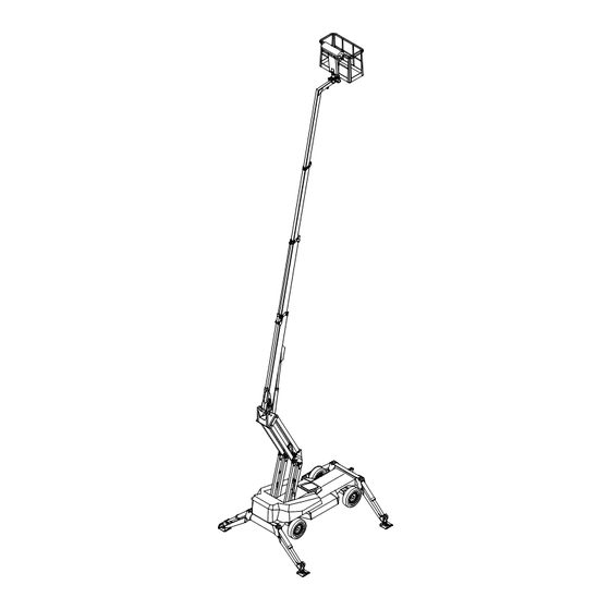
Page 10: General Description Of The Machine
DINO 240RXT 4.2 General description of the machine The denominations of the machine’s essential parts and concepts, which are used later in these instructions, are described on this page. 4.3 Description of the machine’s intended use The Access Platform is exclusively intended for transferring people and tools and acting as a work platform to the limit of its load-bearing capacity and reach (refer to the table of Technical Specifications and Reach Diagram). -
Page 11: General Safety Regulations
DINO 240RXT 5 GENERAL SAFETY REGULATIONS Make yourself familiar with these operation instructions before using the lift! Keep these operating instructions in the place reserved for them. Make sure that all users of the lift are familiar with these instructions. - Page 12 DINO 240RXT Do not use ladders, steps or other similar equipment on the platform. Never throw any objects from the platform. The lift must not be used for transferring goods or persons between different floors or working levels. Never disable the operation of any safety device.
-
Page 13: Instructions For Safe Operation
DINO 240RXT 5.1 !! Instructions for safe operation! Use a safety harness while on the platform. Use hearing protectors when operating the power unit from the chassis panel. Sound pressure level 91 dB. Never load the platform while in the upper position. -
Page 14: Inspections
DINO 240RXT INSPECTIONS A thorough inspection of the lift must be carried out at least once every twelve (12) months. The inspection shall be carried out by a technically trained person who is familiar with the operation and structure of the lift. -
Page 15: Worksite Inspection
DINO 240RXT 7 WORKSITE INSPECTION 1. General information Is the lift suited for the intended job? Is the performance of the lift sufficient for the job? (reach, loadability etc.) Is the position of the lift safe? Is the lighting on the worksite sufficient? 2. -
Page 16: Operation Of Safety Devices
DINO 240RXT OPERATION OF SAFETY DEVICES 1. Support outriggers The safety limit switch RK3 prevents the operation of the outriggers and the driving device when the boom does not rest on the transport support. The switch is located on the transport support. - Page 17 DINO 240RXT 3. Outreach range and overload protection switch The safety limit switches prevent overloading of the lift. At a predetermined position the outreach limit switch RK4 stops extension of the telescope and lowering of the boom. The overload limit switch RK5 backs up if the RK4 for some reason does not work.
- Page 18 DINO 240RXT...
-
Page 19: Operating Controls
DINO 240RXT 9 OPERATING CONTROLS 9.1 CONTROLS ON THE CHASSIS PANEL OK2 Switch lock, positions: 0 - ignition off 1 - power on, operating position 2 - glowing 3 - start Emergency stop push to stop pull to reset Start button of emergency descent system... - Page 20 DINO 240RXT LX-A0 LX-A1...
-
Page 21: Controls On The Platform Panel Ok1
DINO 240RXT 9.2 CONTROLS ON THE PLATFORM PANEL OK1 LX-A0 Control lever (left joystick) LX-A1 Control lever (right joystick) Lx-A0 Lx-A1 Level display of chassis Platform swing fuse Switch lock, positions: 0 - ignition off 1 - power on, operating position... -
Page 22: Measures To Be Taken If The Lift Is At Risk Of Losing Its Stability
DINO 240RXT MEASURES TO BE TAKEN IF THE LIFT IS AT RISK OF LOSING ITS STABILITY Reduced stability can be caused by a fault in the lift, the wind or other lateral force, collapse of the standing base or negligence in providing sufficient support. In most cases one sign of reduced stability is the inclination of the lift. -
Page 23: Start-Up
DINO 240RXT 11 START-UP 1. Ground stability make sure that the ground is even and hard enough to support the lift in a steady level position Max. ground Soil material Density pressure kg/cm² Gravel High density Medium density Loose Sand... - Page 24 DINO 240RXT 3. Starting the engine The machine must be started from the intended operating position. The operation is only possibly from the same location where the machine was started. The machine can only be stopped in the same location where it was started.
- Page 25 DINO 240RXT 1. The electric motor is automatically switched off in 5 seconds after the execution of the movement ends. 4. Driving Make sure that the boom rests on the support and that the outriggers are in the upper position.
- Page 26 DINO 240RXT 3.1. Push (and keep depressed) the button 1 and, using the control lever, activate the desired movement - either raising or lowering the boom. 3.2. Lift the boom to the desired height position. 4. Driving. Push (and keep depressed) the button 2 and activate the desired movement - either driving straight ahead or turning the wheels.
- Page 27 DINO 240RXT 1. Select the desired movement and turn the lever switch. 2. The engine revolutions increase (or the electric motors starts). 3. The selected movement moves at a constant speed.
- Page 28 DINO 240RXT 7. Test the operation of the outreach limit switch RK4 Platform load about 120 kg 100 mm 120 kg PLATFORM LOAD Drive the boom to the horizontal position and extend the telescope with a load of 120 kg on the platform at the spot designated in the drawing.
- Page 29 DINO 240RXT retract the platform to inside the operating range of the RK4 by pushing the "telescope in" - button (S30 or S31)(the red signal light stops flashing) after this the lift may be operated normally The "telescope in" -button (S30 or S31) is always operational when the engine is running.
- Page 30 DINO 240RXT 14. Working a long time in the same position - there is a keyswitch for stopping and starting in both the platform and the chassis control panels When the weather is warm and the platform is kept for a longer period in the same position, it is not necessary to let the engine run continuously.
-
Page 31: Emergency Descent System
DINO 240RXT 12 EMERGENCY DESCENT SYSTEM As a precaution against possible power failure, the lift is equipped with a battery operated emergency descent system. 1. Setup of the system battery 12V 68 Ah hydraulic unit 12 VDC (automatic carger of the battery 12VDC 3A, on the model powered by electric motor ) 2. -
Page 32: Manual Release Of The Parking Brakes
DINO 240RXT 13 MANUAL RELEASE OF THE PARKING BRAKES The parking brakes on both rear wheels can be released mechanically if they fail to be provided with the required hydraulic pressure. Instructions for mechanical release of the parking brakes: Remove the plug Screw a hex screw M12x50 with a nut M12 and a washer to the thread inside the opening. -
Page 33: Special Instructions For Winter Use
DINO 240RXT 14 SPECIAL INSTRUCTIONS FOR WINTER USE the lowest allowed operating temperature of the lift is -20 °C. if the temperature is below zero, let the power unit run for a few minutes before starting the movements start with a few movements to warm-up oil in the cylinders and to ensure proper operation of the... -
Page 34: Measures To Be Taken At The End Of The Working Day
DINO 240RXT 15 MEASURES TO BE TAKEN AT THE END OF THE WORKING DAY 1. Retract the telescope boom completely. 2. Check that the platform is perpendicular to the boom. 3. Lower the boom/platform onto the support on the chassis. -
Page 35: Preparing The Lift For Transport
DINO 240RXT 16 PREPARING THE LIFT FOR TRANSPORT 1. Retract the telescope boom completely. 2. Check that the platform is perpendicular to the boom. 3. Lower the boom/platform onto the support on the chassis. the limit switch on the transport support prevents operation of the support outriggers if the platform is not down 4. - Page 36 DINO 240RXT Notes...
-
Page 37: Instructions For Service And Maintenance
DINO 240RXT 17 INSTRUCTIONS FOR SERVICE AND MAINTENANCE 17.1 GENERAL SERVICE INSTRUCTIONS carry out the servicing and inspection of the lift in accordance with the instructions when it comes to more demanding repair works turn to a specialist or contact the distributor or... -
Page 38: Service And Inspection Instructions
DINO 240RXT 17.2 SERVICE AND INSPECTION INSTRUCTIONS 1. The first service after 20 hours of operation change the pressure and return filter elements 2. Daily service check the oil level in the hydraulics and the engine, top up if necessary... -
Page 39: Lubrication Plan
DINO 240RXT 17.3 LUBRICATION PLAN... -
Page 40: Long-Term Storage
DINO 240RXT EVERY 50 HOURS 1. Bearings of the safety device 2. Bearings of the outrigger cylinders 3. Bearings of the outriggers 4. Bearings of the outrigger foot plates 5. Bearings of the boom and the articulated arms 6. Bearings of the platform 7. - Page 41 DINO 240RXT...
-
Page 42: Load Holding And Load Regulation Valves
DINO 240RXT 17.5 LOAD HOLDING AND LOAD REGULATION VALVES Check of operation 1. To check the tightness of the outrigger cylinder load holding valves measure the height position of the chassis from the floor separately at each outrigger. After a few minutes, measure the height again. -
Page 43: Levelling System Of The Platform
DINO 240RXT 17.6 LEVELLING SYSTEM OF THE PLATFORM A so-called Slave Cylinder System is applied for levelling of the platform: the slave cylinder under the platform is controlled by a master cylinder the platform keeps its level position only if the valves in the system are tight... -
Page 44: Regular Servicing
DINO 240RXT 17.7 REGULAR SERVICING The lift shall be serviced regularly at intervals of 11 - 12 month. Under demanding conditions where moist, corrosive substances or corrosive climate may speed up the deterioration of the structure and induce malfunctions, the inspection must be performed more often and the influence of corrosion and malfunctions must be reduced by using appropriate protective means. - Page 45 DINO 240RXT if required, top up hydraulic oil to the level with the upper edge of the level eye while the lift is in the transport position. 3. Check the hydraulic hoses and pipes Replace any externally damaged hoses or clashed pipes. Check the connections.
- Page 46 DINO 240RXT 6. Inspection of the boom and the chassis extend the telescope and inspect the platform, its attachment, the articulated arms and the boom inspect the boom joints and play of the sliding pads, readjust if necessary. Lubricate the sliding...
- Page 47 DINO 240RXT 7. Inspection of the axles check the attachment of the axles check the bearings of the oscillating axle and the condition of the cushion rubbers 8. Inspection of the safety devices check the attachment and the external condition of the limit switches...
- Page 48 DINO 240RXT 9. Operation of the safety devices while they are controlled from the chassis control panel lift the platform slightly up from the transport position the support outriggers must not work lift the boom and test the following: 1. emergency stop 2.
-
Page 49: Testing The Outreach Limit Switch (Rk4)
DINO 240RXT Now: the lifting of the boom should be operational - the lowering of the boom must NOT be operational the retraction of the telescope should be operational - the extension of the telescope must NOT be operational 17.7.1 TESTING THE OUTREACH LIMIT SWITCH (RK4) Put a carefully weighed load (80 kg) on the platform. - Page 50 DINO 240RXT Extend the telescope until it stops (do not correct the position of the platform). STROKE Measure the length of the protruding part of the telescope extension (stroke). The length shall be 1,800 mm ±50 mm. Make sure that a red signal light on the platform is flashing and that the following text is on the display:...
-
Page 51: Testing The Overload Limit Switch (Rk5)
DINO 240RXT 17.7.2 TESTING THE OVERLOAD LIMIT SWITCH (RK5) The overload limit-switch RK5 will back up if the outreach limit switch RK4 for some reason would not work. Disable the RK4 by connecting for the test the terminals 64 and 70 in the chassis control panel with a jumper lead. - Page 52 DINO 240RXT Extend the telescope until it stops. (Do not correct the position of the platform). STROKE Measure the length of the protruding part of the telescope extension (stroke). The length shall be 2100 mm ±50 mm. If the protruding part is too long, adjust the limit switch and secure its position with a seal.
-
Page 53: Adjustment Of Outreach Limit Switch (Rk4) And The Overload Limit Switch (Rk5)
DINO 240RXT 17.7.3 ADJUSTMENT OF OUTREACH LIMIT SWITCH (RK4) AND THE OVERLOAD LIMIT SWITCH (RK5) PRESSURE SPRING LIMIT SWITCHES RK4 AND RK5 ARTICULATED ARM LIFTING CYLINDER Always check the operation of both limit switches in connection with the service. Put a carefully weighed load (80 kg) on the platform. Place it at a distance of 100 mm from the rear edge of the platform. - Page 54 DINO 240RXT Lift and lower the rear edge of the platform using the position control. 1. Lowering the rear edge of the platform 2. Lifting the rear edge of the platform Drive the platform with the position control to a horizontal position so that that the last stage of the adjustment procedure is lifting of the rear edge.
- Page 55 DINO 240RXT Adjust the RK4 to closer than the RK5. At first retract the telescope and after that extend it until it stops. (Do not correct the position of the platform). STROKE Measure the length of the protruding part of the telescope extension (stroke). The length shall be 1,800 mm ±50 mm.
- Page 56 DINO 240RXT 10. Measuring the pressure connect the pressure gauge to the measuring point the max. pressure with warm (40 - 60 °C) oil is 20 -20,5 MPa (200 -205 bar) the turning pressure is 6 MPa (60 bar)
- Page 57 DINO 240RXT Opening pressure of the brakes connect the pressure gauge to the measuring point during the travelling the pressure shall be 2,5 MPa 11. Check the operating controls on the platform check the overall condition of the electric appliances inside the box and spray with moisture...
- Page 58 DINO 240RXT Notes...
-
Page 59: Inspection Instructions
DINO 240RXT 18 INSPECTION INSTRUCTIONS All lifting equipment and lifting gear used at a construction site must always be inspected before use. The lifts and related lifting gear used on a work site shall be subjected to a regular maintenance inspection;... -
Page 60: Sample Of Inspection Protocol For The Access Platform
DINO 240RXT 18.2 SAMPLE OF INSPECTION PROTOCOL FOR THE ACCESS PLATFORM... - Page 61 DINO 240RXT...
-
Page 62: Daily Inspection (Start-Up Inspection)
DINO 240RXT 18.3 DAILY INSPECTION (START-UP INSPECTION) To be always performed at a new work site and in the beginning of every working day. The inspection is performed by the user. In the inspection attention shall be paid to the following... -
Page 63: Monthly Inspection (Maintenance Inspection)
DINO 240RXT 18.4 MONTHLY INSPECTION (MAINTENANCE INSPECTION) The inspection shall be performed by a person who is well familiar with the lift. Task list for inspection: perform the measures of the daily inspection check the attachment points of the boom and the platform... -
Page 64: Annual Inspection (Regular Inspection)
DINO 240RXT 18.5 ANNUAL INSPECTION (REGULAR INSPECTION) The inspection shall be performed by a skilled technician or an expert inspection body with documented evidence of competence (see point “Inspections”). In the inspection special attention has to be paid to the condition of the steel structures, the safety devices and the operating system. - Page 65 DINO 240RXT - directional valves on the chassis check that the valves of the support outriggers and the driving device work properly and no movements are executed when the spools are in the neutral position - electro-hydraulic rotary adaptor check the adaptor for tightness...
- Page 66 DINO 240RXT check the condition of the boom joint check the bearing and the pin of the boom joint and the locking of the pin check the condition and attachment of the articulated arm joint pins and bearings check the support outriggers and their footplates...
-
Page 67: Extraordinary Inspection
DINO 240RXT inspect the chassis general condition check the axle and its attachment to the chassis check the rims, the tightness of the wheel bolts, the tyres and the tyre pressure check the condition of the transport support of the boom perform a test run, test all operating controls, control the outreach according to the instructions (see point “Testing the outreach limit switch”) -
Page 68: Test Loading Instructions For Regular Inspection
DINO 240RXT 18.7 TEST LOADING INSTRUCTIONS FOR REGULAR INSPECTION 1. Place the lift on an even surface with good carrying capacity. Drive the outriggers to their lowest position (the minimum support width). 2. Raise the boom, turn it to the side from the transport support and lower it to the ground. -
Page 69: Fault Finding
DINO 240RXT FAULT FINDING FAULT REMEDY 1. The engine does not start The main current is not connected. Switch on the main switch and activate the current feed by depressing the pedal switch (OK1) or by executing some movement (OK2). - Page 70 DINO 240RXT FAULT REMEDY 6. Disturbance of platform movements - only one of the movements is operational Irregular and indefinite malfunctions. Check that the hydraulic oil and the filters have been changed. Thoroughly clean the solenoid valve spools and housings (requires utmost cleanliness - not all contaminants can be spotted with the naked eye).
- Page 71 DINO 240RXT FAULT REMEDY 10. Telescope retracts slowly The load regulation valve leaks. For remedy, refer to item 5. 11. Platform drifts backward Double load regulation valve on the bottom side For remedy, refer to item 5. is leaking. Load regulation valve under the platform is For remedy, refer to item 5.
- Page 72 DINO 240RXT FAULT REMEDY 15. Driving device does not operate The brakes drag. Check the opening pressure of the brakes and adjust to 2,5 MPa, if necessary. Naturally the possible reasons for malfunctions are many, but the following are the most common:...
-
Page 73: Operation Of Electric Components
DINO 240RXT 20 OPERATION OF ELECTRIC COMPONENTS 20.1 MAIN CONTROL CENTRE (PK) K1: Start contactor of electric motor M1(optional extra) K2: Contactor of EMERGENCY STOP button. Switches the power supply on/off according to the position of the EMERGENCY STOP button. - Page 74 DINO 240RXT K24: Auxiliary relay for emergency descent. Draws as the emergency descent button S11 or S13 is depressed. Switches on the voltage to the emergency descent unit solenoid and the emergency descent valves 9, 10 and 11. K40: Changeover relay for the control voltage.
-
Page 75: Control Centre 2 (Ok2)
DINO 240RXT F11: Module XS-A0 10A (PK). F12: Module XS-A0 10A (PK). XP-A0 Power supply unit. Bus module used for controlling the propo valves and relays and as a connection terminal for the sensors. XS-A0: Signal unit: Bus module used for controlling the relays and as a connection terminal for the sensors. -
Page 76: Control Centre 1 (Ok1)
DINO 240RXT 20.3 CONTROL CENTRE 1 (OK1) AD: Level display of the lift. Indicates the level position of the machine with illuminated led-lights. As the machine is in the level position, only the red led in the middle of the display will be illuminated. - Page 77 DINO 240RXT S26: Button for driving with raised boom. As the button is depressed, the boom can be raised during the driving to the level position or the machine can be driven with the boom in the horizontal position. During the driving the outrigger limit-switches are bypassed with this button.
-
Page 78: Limit Switches
DINO 240RXT 20.4 LIMIT SWITCHES RK3: Prevents the operation of the outriggers and the driving device if the boom does not rest on the transport support. RK4: Safety limit-switch for the adjusted operating range. RK5: Backup limit-switch for the safety limit-switch RK4. As this limit-switch operates, the bus is... -
Page 79: Chassis Control Centre (Ak)
DINO 240RXT 20.5 CHASSIS CONTROL CENTRE (AK) F7: Outriggers, feed to XP-A1- module (10 A). F14: Outriggers, feed to XP-A1- module (10 A). K30: Control relay. Control relay for the outrigger 1, upwards. K31: Control relay. Control relay for the outrigger 1, downwards. -
Page 80: Other Markings
DINO 240RXT 20.6 OTHER MARKINGS ALT: Alternator on the combustion engine. B1: Battery 12VDC 68Ah. E1: Thermo-relay for the engine M1. GP: Glow plugs. Switches off the fuel supply from the feeder pump as the solenoid is not energized. LS: Inclination sensor. -
Page 81: Electric Components
DINO 240RXT 20.7 ELECTRIC COMPONENTS REF. PART NR. DESCRIPTION 48.3472 LEVELLING DISPLAY OF CHASSIS 48.2325 BATTERY 48.3039 200A FUSE F2-F5, F7, 48.647 10A FUSE F10-F12, F14 48.3038 16A FUSE 48.3395 LEAD PROTECTION 48.3037 3A FUSE 48.3036 AUTOMATIC FUSE 4A H1, H2, H3, 48.3469+48.3470... - Page 82 DINO 240RXT 48.616 + 48.1007 LEVER SWITCH 48.616 + 48.1007 LEVER SWITCH 48.616 + 48.1007 LEVER SWITCH 48.616 + 48.1007 LEVER SWITCH 48.616 + 48.1007 LEVER SWITCH 48.616 + 48.1007 LEVER SWITCH 48.616 + 48.1007 LEVER SWITCH 48.616 + 48.1007 LEVER SWITCH 48.616 + 48.1007...
-
Page 83: Electric Diagram 24021
DINO 240RXT 21 ELECTRIC DIAGRAM 24021 ->... - Page 84 DINO 240RXT...
- Page 85 DINO 240RXT...
- Page 86 DINO 240RXT...
- Page 87 DINO 240RXT...
- Page 88 DINO 240RXT...
- Page 89 DINO 240RXT...
- Page 90 DINO 240RXT...
- Page 91 DINO 240RXT...
- Page 92 DINO 240RXT...
- Page 93 DINO 240RXT...
- Page 94 DINO 240RXT...
- Page 95 DINO 240RXT...
- Page 96 DINO 240RXT...
- Page 97 DINO 240RXT...
- Page 98 DINO 240RXT...
- Page 99 DINO 240RXT...
- Page 100 DINO 240RXT...
- Page 101 DINO 240RXT...
- Page 102 DINO 240RXT...
- Page 103 DINO 240RXT...
- Page 104 DINO 240RXT...
- Page 105 DINO 240RXT...
- Page 106 DINO 240RXT...
- Page 107 DINO 240RXT Notes...
-
Page 108: Hydraulic Diagram; Drive Transmission
DINO 240RXT 22 HYDRAULIC DIAGRAM; DRIVE TRANSMISSION To the disengagement valve of the brakes hydraulic diagram; boom operation, pos. 9 SPARE PART REF. NO. ITEM 47.2081 DOUBLE PUMP 47.2845 FLOW DIVIDER VALVE 47.2861 FLOW DIVIDER VALVE 47.2326 HYDRAULIC MOTOR 47.2327... -
Page 109: Hydraulic Components
DINO 240RXT 23 HYDRAULIC COMPONENTS Dino 240 RXT, BOOM OPERATION, STANDARD MACHINE NO. 24013--- REF. NO. SPARE PART NO. ITEM 47.2081 DOUBLE PUMP 47.2855 SOLENOID VALVE 47.2871 MOUNTING PLATE 47.2850 SOLENOID VALVE 48.3449 PYÖRIVÄLIITIN 47.2852 CHECK VALVE 47.2847 PROPORTIONAL VALVE 47.2846... -
Page 110: Hydraulic Diagram; Boom Operation No. 24013
DINO 240RXT 24 HYDRAULIC DIAGRAM; BOOM OPERATION No. 24013---... -
Page 111: Hydraulic Components
DINO 240RXT 25 HYDRAULIC COMPONENTS Dino 240 RXT, BOOM OPERATION, WITH OPTIONAL EQUIPMENT NO. 24010--- REF. NO. SPARE PART NO. ITEM 47.2081 DOUBLE PUMP, REXROTH 47.2855 SOLENOID VALVE 47.2871 MOUNTING PLATE 47.2850 SOLENOID VALVE 48.3449 ROTARY ADAPTOR 12-RING 47.2852 CHECK VALVE 47.2847... -
Page 112: Hydraulic Diagram; Boom Operation, With Optional Equipment No
DINO 240RXT 26 HYDRAULIC DIAGRAM; BOOM OPERATION, WITH OPTIONAL EQUIPMENT No. 24010---... - Page 113 DINO 240RXT Notes...
Need help?
Do you have a question about the 240RXT and is the answer not in the manual?
Questions and answers