Table of Contents
Advertisement
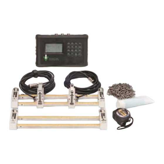
Quick Links
Advertisement
Table of Contents

Related Manuals for VorTek U44 Series


Summary of Contents for VorTek U44 Series
- Page 1 Series U44 Instruction Manual VorTek Series U44 Ultrasonic Flow Meter Instruction Manual M-000-00090 Rev 8/2021 8475 W I-25 Frontage Rd Suite 300 Longmont, CO 80504 (303) 682-9999 (888) 386-7835 Fax (303) 682-4368 http://www.vortekinst.com M-000-00090...
- Page 2 Series U44 Instruction Manual Notice Thank you for choosing our Ultrasonic Flow Meter. Please read the instruction manual carefully before you use the flow meter to avoid damaging the flow meter or improper use. Warning May cause injury. Attention May damage the flow meter. Some of the instructions may be different for the flow meter you purchased, depending on the configuration requirements.
- Page 3 Series U44 Instruction Manual Product Components Be sure to inspect all product components before installing the flow meter. Check to see if the spare parts are in accordance with the packing list. Make sure that there is no damage to the enclosure due to a loose screw or wire or other damage that may have occurred during transportation.
-
Page 4: Table Of Contents
Series U44 Instruction Manual Table of Contents Product Overview ............................7 Introduction ............................7 Features of the Ultrasonic Flow Meter ....................7 Theory of Operation ........................... 7 Applications ............................8 U44 Specifications ..........................8 Installation ..............................10 Wire Connections ..........................10 2.1.1 U44 Connections ........................ - Page 5 Series U44 Instruction Manual Using the Setup Menus ........................22 3.2.1 Programming the Flow Meter ....................23 3.2.2 Output Menu ..........................23 3.2.3 Display Menu ........................... 24 3.2.4 Totalizer #1 Menu ........................24 3.2.5 Totalizer #2 Menu ........................25 3.2.6 Energy Menu ..........................
- Page 6 Series U44 Instruction Manual 6.3.1 HL Protocol ..........................38 6.3.2 Modbus Protocol ........................40 Appendix 2 – Flow Application Data ....................... 45 Sound Velocity and Viscosity for Fluids Commonly Used .............. 45 Sound Velocity for Various Materials Commonly Used ..............45 Sound Velocity in Water (1 atm) at Different Temperatures ............
-
Page 7: Product Overview
Series U44 Instruction Manual 1. Product Overview Introduction This product is a portable, clamp-on type ultrasonic flow meter using transfer time technology. The clamp-on type ultrasonic flow meter is easy to attach and has no need to cut off the pipe, which saves you a lot of trouble and cost. -
Page 8: Applications
Series U44 Instruction Manual Applications ⚫ Water, sewage (with low particle content), and seawater; ⚫ Water supply and drainage water; ⚫ Power plants (nuclear power plant, thermal, and hydropower plants), heat energy, boiler feed water, and energy management system; ⚫ Metallurgy and mining applications (cooling water and acid recovery, for example);... - Page 9 Series U44 Instruction Manual Transmitter: -40 °F ~ 140 °F (- 40 ℃ ~ 60 ℃). Transmitter Temperature Humidity Up to 99% RH, non-condensing. Physical Specifications Transmitter NEMA13, IP54 Encapsulated design, IP68 Transducer Standard / Maximum cable length: 16ft (5m) M-000-00090...
-
Page 10: Installation
Series U44 Instruction Manual 2. Installation Wire Connections 2.1.1 U44 Connections 2.1.2 Breakout Box Connections Refer to the below diagram for specific connection: Sign Description 4 - 20 mA RS-485 Output IN2+ Temperature Sensor Outline + IN2- Temperature Sensor Outline - Temperature Sensor Outline Grounding M-000-00090... -
Page 11: Powering On
Series U44 Instruction Manual IN1+ Temperature Sensor Inline + IN1- Temperature Sensor Inline - Temperature Sensor Inline Grounding Powering On As soon as the flow meter is switched on, the system will run automatically according to the last input parameters. After installation, when the system is switched on, gain adjustment can be monitored in the Run Mode Screens. -
Page 12: Transducer Spacing
Series U44 Instruction Manual Conditions Upstream Straight Run Downstream Straight Run General Conditions Elbow Partially Open Valve Reduced Pipe Expanded Pipe ⚫ On the horizontal pipe, the transducer should be mounted on the 9 o’clock and 3 o’clock positions of the pipe, avoiding the positions of 6 o’clock and 12 o’clock, in case of signal attenuation caused by the pipe, sediment at the bottom, or bubble cavitation on the pipe. -
Page 13: Method
Series U44 Instruction Manual 2.3.4 V Method The V method is considered the standard method. It is convenient to use, but still requires proper installation of the transducers, contact on the pipe at the centerline, and equal spacing on either side of the centerline. This is recommended for carbon steel pipes. -
Page 14: W Method
Series U44 Instruction Manual 2.3.5 W Method The signal transmitted in a W method may be stronger than with the V method on smaller diameter pipes. This method is recommended for pipes with diameters of 3 inches (75 mm) and below or PVC pipes. Side view Section Top View... -
Page 15: Z Method
Series U44 Instruction Manual 2.3.6 Z Method The signal transmitted in a Z method installation has less attenuation than a signal transmitted with the V or W methods. When pipes are too large, there is some suspended solid in the fluid or the scaling and liner are too thick. This is why the Z method utilizes a directly transmitted (rather than reflected) signaling which transverses the liquid only once. -
Page 16: Measurement Site Selection
Series U44 Instruction Manual 1. Cable 2. Connector 3. Lock-nut 4. Ball valve 5. Mounting Base 6. Transducer probe 2.4.1 Measurement Site Selection When selecting a measurement site, it is important to select an area where the fluid flow profile is fully developed to guarantee a highly accurate measurement. -
Page 17: Transducer Mounting Instructions
Series U44 Instruction Manual 2.4.2 Transducer Mounting Instructions 1. Drill a 24mm diameter hole at the measuring point. Be sure to center of the hole is aligned to match the location for the center of the transducer. Weld the coupling adapter in place. 2. -
Page 18: Method
Series U44 Instruction Manual 2.4.3 V Method The V method is considered as the standard method. It is convenient to use, but still requires proper installation of the transducers, contact on the pipe at the pipe’s centerline, and equal spacing on either side of the centerline. -
Page 19: Signal Quality (Q Value)
Series U44 Instruction Manual Adjust the transducer to the best position and check to ensure that enough sonic coupling compound was applied during installation to obtain the maximum signal strength. The system normally requires a signal strength over 75.0, which is detected from both upstream and downstream directions. - Page 20 Series U44 Instruction Manual transducer is mounted at the pipe’s centerline on the same diameter. Pay special attention to pipes formed by steel rolls (pipe with seams), since such pipe is always irregular. If the signal strength is always displayed as 0.00, that means there is no signal detected. Thus, it is necessary to check that the parameters (including all the pipe parameters) have been entered accurately.
-
Page 21: Display & Menus
Series U44 Instruction Manual 3. Display & Menus Display & Keypad 3.1.1 Keypad Functions Numbers “0~9” and input numbers or codes. goes back to the previous menu. opens the next menu. selects a menu or value. 3.1.2 Keypad Operation The flow meter’s digital electronics allow you to set, adjust, and monitor system parameters and performance. A full range of commands are available through the display/keypad. -
Page 22: Using The Setup Menus
Series U44 Instruction Manual Using the Setup Menus M-000-00090... -
Page 23: Programming The Flow Meter
Series U44 Instruction Manual 3.2.1 Programming the Flow Meter 1. Enter the Setup Menu by pressing the ENTER key until prompted for a password. (All outputs are disabled while using the Setup Menus.) 2. Use the number keys to enter the password (1234 is the factory-set password). When the password is correctly displayed, the Setup Menus will be displayed. -
Page 24: Display Menu
Series U44 Instruction Manual 3.2.3 Display Menu 3.2.4 Totalizer #1 Menu M-000-00090... -
Page 25: Totalizer #2 Menu
Series U44 Instruction Manual 3.2.5 Totalizer #2 Menu 3.2.6 Energy Menu M-000-00090... -
Page 26: Fluid Menu
Series U44 Instruction Manual 3.2.7 Fluid Menu 3.2.8 Units Menu M-000-00090... -
Page 27: Time & Date Menu
Series U44 Instruction Manual 3.2.9 Time & Date Menu 3.2.10 Diagnostics Menu M-000-00090... -
Page 28: Calibration Menu
Series U44 Instruction Manual 3.2.11 Calibration Menu 3.2.12 Password Menu M-000-00090... -
Page 29: Engineer Menu
Series U44 Instruction Manual 3.2.13 Engineer Menu M-000-00090... -
Page 30: Engineer Menu 2
Series U44 Instruction Manual 3.2.14 Engineer Menu 2 M-000-00090... -
Page 31: Operation Instructions
Series U44 Instruction Manual 4. Operation Instructions System Normal Identification If the letter "*R" displays on the screen, it indicates system normal. If the letter "D" is displayed, it indicates the system is adjusting the signal gain prior to the measurement. It means system normal. -
Page 32: System Lock
Series U44 Instruction Manual System Lock System lock is intended to prevent operation error due to tampering by unauthorized personnel. The Password Menu is for system lock. Unlock it by using the selected password only. If "lock” is displayed on the screen, then enter the correct password. -
Page 33: Totalizer Pulse Output
Series U44 Instruction Manual Totalizer Pulse Output Each time the flow meter reaches a unit flow, it may generate a totalizer pulse output to a remote counter. The totalizer pulse output can be transmitted through Open Collector Transistor (OCT) or a relay. Therefore, it is necessary to configure OCT and the relay accordingly. -
Page 34: Sd Card Operation
Series U44 Instruction Manual The results are automatically saved in EEPROM and won’t be lost when the power is turned off. 4.10 SD Card Operation 4.10.1 Specifications Data collection interval: any interval settings from 1 to 3600 seconds are OK according to the requirements. Data content: date and time, flow rate, flow velocity, total flow, positive totalizer, negative totalizer. -
Page 35: Troubleshooting
Series U44 Instruction Manual 5. Troubleshooting Determine Fault: Please confirm there are no issues with First check Items above before continuing. Symptom: No/Low Signal Quality Verify the meter is installed correctly and that the application has been configured correctly by using the tables below. - Page 36 Series U44 Instruction Manual Warning! Always remove main power before disassembling any part of the mass flow meter. Use hazardous area precautions if applicable. Static sensitive electronics - use electro-static discharge precautions. First Check Items: Power and Wiring Correct ...
- Page 37 Zero Cutoff = Yes or No Record the following values from the Engineer Menu 2 with the meter installed: (use password 209. to access) Cal Mode = Vortek Instruments, LLC 8475 West I-25 Frontage Rd Longmont, CO 80504 USA www.vortekinst.com...
-
Page 38: Appendix 1 - Serial Interface Network Use And Communications Protocol
Series U44 Instruction Manual 6. Appendix 1 – Serial Interface Network Use and Communications Protocol Overview The flow meter is provided with a UART protocol and can also be operated by using RS-485 Modbus. The two structures that can be used for networking are applying the analog current output method or directly applying the UART communication method of the flow meter. - Page 39 Series U44 Instruction Manual RT-(cr)(lf) Return to Total (Cold Quantity) ±ddddddd.d±d(cr) RER(cr)(lf) Return to Energy Transient Quantity ±d.ddddddE±dd(cr) Return Analog Input Value RAl(cr)(lf) ±d.ddddddE±dd(cr) (temperature, pressure, and etc.) Return Analog Input Value RA2(cr)(lf) ±d.ddddddE±dd(cr) (temperature, pressure, and etc.) RID(cr)(lf) Return to Meter Address Code ddddd(cr) 5-bit length RSS(cr)(lf) Return to Signal Status...
-
Page 40: Modbus Protocol
Series U44 Instruction Manual 6.3.2 Modbus Protocol This Modbus-I Protocol uses RTU transmission mode. The Verification Code uses CRC-16-IBM (polynomial is X16+X15+X2+1, shield character is 0xA001) which is gained by the cyclic redundancy algorithm method. Modbus-I RTU mode uses hexadecimals to transmit data. 1. - Page 41 Series U44 Instruction Manual The slave returns the data frame format (function code 0x06): Slave Address Operation Register Address Register Data Verify Code Function Code 1 byte 1 byte 2 bytes 2 bytes 2 bytes 0x01 ~ 0xF7 0x06 0x0000 ~ 0xFFFF 0x0000 ~ 0xFFFF CRC (Verify) The range of flow meter addresses 1 to 247 (Hexadecimal: 0x01 ~ 0xF7) and can be checked in the Output Menu.
- Page 42 Series U44 Instruction Manual Flow meter returned error code is: 0x01 0x83 0x02 0xC0 0xF1 Flow Meter Address Error Code Error Extended Code CRC Verify Code 5. Modbus Register Address List The flow meter Modbus Register has a read register and a write single register. Read Register Address List (use 0x03 function code to read) Register Read...
- Page 43 Series U44 Instruction Manual Energy flow – low word $0011 40018 32 bits real Energy flow – high word $0012 40019 Energy total (hot) –low word $0013 40020 32 bits real Energy total (hot) –high word $0014 40021 Energy total (hot) – exponent $0015 40022 16 bits int.
- Page 44 Series U44 Instruction Manual $0043 40068 Instrument address – low word 32 bits int. $0044 40069 Instrument address – high word $0045 40070 Serial number – char 1,2 String $0046 40071 Serial number – char 3,4 $0047 40072 Serial number – char 5,6 String $0048 40073...
-
Page 45: Appendix 2 - Flow Application Data
Series U44 Instruction Manual 7. Appendix 2 – Flow Application Data Sound Velocity and Viscosity for Fluids Commonly Used Sound Ethanol 1168 Fluid Viscosity Velocity (m/s) Alcohol 1440 Water 20℃ 1482 Glycol 1620 Water 50℃ 1543 0.55 Glycerin 1923 1180 Water 75℃... -
Page 46: Sound Velocity In Water (1 Atm) At Different Temperatures
Series U44 Instruction Manual Sound Velocity in Water (1 atm) at Different Temperatures T (℃) V (m/s) T (℃) V (m/s) T (℃) V (m/s) 1402.3 1517.7 1554.3 1407.3 1519.7 1554.5 1412.2 1521.7 1554.7 1416.9 1523.5 1554.9 1421.6 1525.3 1555.0 1426.1 1527.1 1555.0...
Need help?
Do you have a question about the U44 Series and is the answer not in the manual?
Questions and answers