
Related Manuals for VorTek MT160


Summary of Contents for VorTek MT160
- Page 1 MT160 Ultrasonic Thickness Gauge Instruction Manual Document Number 800103 Rev A 8475 W I-25 Frontage Rd Suite 300 Longmont, CO 80504 (303) 682-9999 (888) 386-7835 Fax (303) 682-4368 http://www.vortekinst.com...
-
Page 2: Table Of Contents
MT160 Instruction Manual 1 Overview ........3 1.1 Product Specifications .......... 3 1.2 Main Functions ............. 4 1.3 Measuring Principle ..........4 1.4 Configuration ............5 1.5 Operating Conditions ..........5 2 Features ........6 2.1 Main Screen ............7 2.2 Keypad Definitions .......... - Page 3 MT160 Instruction Manual 5 Servicing ........29 6 Transport and Storage ....29 Appendix A Sound Velocities ..30 Appendix B App. Notes ....31 800103...
-
Page 4: Overview
MT160 Instruction Manual 1 Overview The model MT160 is a digital ultrasonic thickness gauge. Based on the same operating principles as SONAR, the instrument is capable of measuring the thickness of various materials with accuracy as high as 0.1mm/0.01 millimeters. It is suitable for a variety of metallic and non-metallic materials. -
Page 5: Main Functions
MT160 Instruction Manual 1.2 Main Functions 1) Capable of performing measurements on a wide range of material, including: metals, plastic, ceramics, composites, epoxies, glass and other acoustically conductive materials. 2) Transducer models are available for special applications, including: high temperature or coarse material applications. -
Page 6: Configuration
MT160 Instruction Manual Where: H-Thickness of the test piece. v-Sound Velocity in the material. t-The measured round-trip transit time. 1.4 Configuration Item Quantity Note Standard Main body Configuration Transducer Model: N05 Couplant Instrument Case Optional Transducer: N02 See Table 3-1... -
Page 7: Features
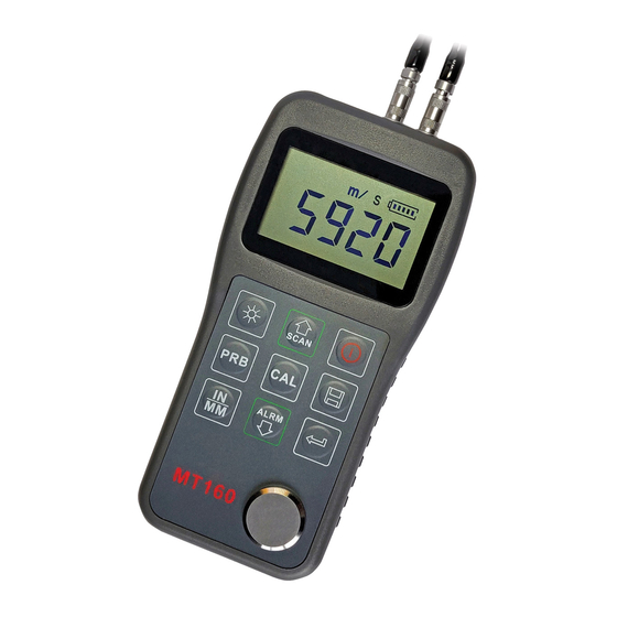
MT160 Instruction Manual 2 Features ULTRASONIC THICKNESS GAUGE POWER: 2 X 1.5V MT16 Figure 1: Product Features Main Body Keypad LCD Display Transmitter Socket Receiver Socket Probe Zero-Disc Communication Port Label Battery Cover Probe 800103... -
Page 8: Main Screen
MT160 Instruction Manual 2.1 Main Screen Figure 2: Main Screen 1. Coupling Status: Indicates the coupling status. While the gauge is taking a measurement, the coupling status indicator should be on. If it is not on or not stable, the gauge is having difficulty achieving a stable measurement, and the thickness value displayed will most likely be erroneous. -
Page 9: Keypad Definitions
MT160 Instruction Manual 2.2 Keypad Definitions Turn the instrument Sound velocity on/off calibration Turn on/off the EL Enter backlight Probe-Zero operation Plus; Turn on/off Scan Mode Unit switch between Minus; Metric and Imperial Turn on/off Beep system Mode Data Save or Data... -
Page 10: Preparation
MT160 Instruction Manual 3 Preparation 3.1 Transducer Selection The gauge is inherently capable of performing measurements on a wide range of materials, from various metals to glass and plastics. Different types of material, however, will require the use of different transducers. Choosing the correct transducer for a job is critical to being able to easily perform accurate and reliable measurements. - Page 11 MT160 Instruction Manual echo. Higher frequency ultrasound is absorbed and scattered more than ultrasound of a lower frequency. While it may seem that using a lower frequency transducer might be better in every instance, low frequencies are less directional than high frequencies.
- Page 12 MT160 Instruction Manual The transducer is the “business end” of the instrument. It transmits and receives ultrasonic sound waves that the instrument uses to calculate the thickness of the material being measured. The transducer connects to the instrument via the attached cable, and two coaxial connectors.
- Page 13 MT160 Instruction Manual hold the transducer in place. Moderate pressure is sufficient, as it is only necessary to keep the transducer stationary, and the wear face seated flat against the surface of the material being measured. Table 3-1: Transducer Selection...
-
Page 14: Condition And Preparation Of Surfaces
MT160 Instruction Manual 3.2 Condition and Preparation of Surfaces In any ultrasonic measurement scenario, the shape and roughness of the test surface are of paramount importance. Rough, uneven surfaces may limit the penetration of ultrasound through the material, and result in unstable, and therefore unreliable, measurements. -
Page 15: Operation
MT160 Instruction Manual longer lies directly beneath the transducer. 4 Operation 4.1 Power On/Off The instrument is turned on by pressing the key. Figure 5: LCD Display with Power Turned On The gauge can be turned off by pressing the key while it is on. - Page 16 MT160 Instruction Manual corrected for in all subsequent measurements. The instrument may be “zeroed” by performing the following procedure: 1) Plug the transducer into the instrument. Make sure that the connectors are fully engaged. Check that the wear face of the transducer is clean and free of any debris.
-
Page 17: Sound Velocity Calibration
MT160 Instruction Manual 4.3 Sound Velocity Calibration In order for the gauge to make accurate measurements, it must be set to the correct sound velocity for the material being measured. Different types of material have different inherent sound velocities. If the gauge is not set to the correct sound velocity, all of the measurements the gauge makes will be erroneous by some fixed percentage. - Page 18 MT160 Instruction Manual coupling status indicator should appear steady. 4) Having achieved a stable reading, remove the transducer. If the displayed thickness changes from the value shown while the transducer was coupled, repeat step 3. 5) Press the key to activate the calibration mode. The MM (or IN) symbol should begin flashing.
- Page 19 MT160 Instruction Manual are flashing. 3) Use the key and the key to adjust the sound velocity value up or down, until it matches the sound velocity of the material to be measured. You can also press the key to switch among the predefined velocities that are most commonly used.
-
Page 20: Making Measurements
MT160 Instruction Manual 4) Having achieved a stable reading, remove the transducer. If the displayed thickness changes from the value shown while the transducer was coupled, repeat step 3. 5) Press the key. The MM (or IN) symbol should begin flashing. - Page 21 MT160 Instruction Manual commonly called “couplant”. This fluid serves to “couple”, or Figure 6: MT160 Prior to New Measurement transfer, the ultrasonic sound waves from the transducer, into the material, and back again. Before attempting to make a measurement, a small amount of couplant should be applied to the surface of the material being measured.
- Page 22 “zeroed” and set to the correct sound velocity, the number in the display will indicate the actual thickness of the material directly beneath the transducer. See Figure 8 for an example of what to expect on the MT160’s display when taking a measurement. 800103...
- Page 23 MT160 Instruction Manual Figure 8: Measuring Wall Thickness of a PVC Pipe If the coupling status indicator does not appear, is not stable, or the numbers on the display seem erratic, check to make sure that there is an adequate film of couplant beneath the transducer, and that the transducer is seated flat against the material.
-
Page 24: Scan Mode
MT160 Instruction Manual last measurement made. Note:Occasionally, a small film of couplant will be drawn out between the transducer and the surface as the transducer is removed. When this happens, the gauge may perform a measurement through this couplant film, resulting in a measurement that is larger or smaller than it should be. - Page 25 MT160 Instruction Manual measurement it finds. The transducer may be “scrubbed” across a surface, and any brief interruptions in the signal will be ignored. Be sure there is always an adequate film of couplant between the transducer and the material being measured to ensure accurate measurements while “scrubbing”.
-
Page 26: Changing Resolution
The instrument will display the status of the scan mode on the main screen. 4.6 Changing Resolution The MT160 has selectable display resolution, which is 0.1mm or 0.01mm. Press down the key while turning on the gauge to switch the resolution between “High”... - Page 27 MT160 Instruction Manual added as the last record of the file. To change the destination file to store the measured values, follow these steps: 1) Press the key to activate the data logging functions. The instrument will display the current file name and the total record count of the file.
-
Page 28: Beep Mode
MT160 Instruction Manual 4.8.3 Viewing/deleting stored record This function provides the user with the ability to view/delete a record in a desired file previously saved in memory. Follow these steps to perform this action. Press the key to activate the data logging functions. The instrument will display the current file name and the total record count of the file. -
Page 29: El Backlight
MT160 Instruction Manual 4.10 EL Backlight With the background light, it is convenient to work in dark conditions. Press the key after the device has been powered on to switch on or switch off the background light. The EL light will consume more power so turn it on only when necessary. -
Page 30: System Reset
Return Material Authorization (RMA) number first. To obtain an RMA number and the correct shipping address, submit a request through VorTek Instruments, LLC website, vortekinst.com, or contact Customer Service at: 888-386-7835 or 303-682-9999 in the USA, When contacting Customer Service, be sure to have the meter serial number and model code. - Page 31 MT160 Instruction Manual Appendix A: Sound Velocities Material Sound Velocity Longitudinal Wave in/µs Aluminum 0.250 6340-6400 0.233 Steel, common 5920 0.226 Steel, stainless 5740 0.173 Brass 4399 0.186 Copper 4720 0.233 Iron 5930 0.173-0.229 Cast Iron 4400-5820 0.094 Lead 2400 0.105...
- Page 32 MT160 Instruction Manual 0.092 Polystyrene 2337 0.230 Porcelain 5842 0.094 2388 0.222 Quartz glass 5639 0.091 Rubber, vulcanized 2311 0.056 Teflon 1422 0.058 Water 1473 Appendix B: Applications Notes Measuring pipe and tubing When measuring a piece of pipe to determine the thickness of the pipe wall, orientation of the transducers is important.
- Page 33 MT160 Instruction Manual Figure 10: Transducer Orientation Measuring hot surfaces The velocity of sound through a substance is dependant upon its temperature. As materials heat up, the velocity of sound through them decreases. In most applications with surface temperatures less than 100℃, no special procedures need to be observed. At...
- Page 34 MT160 Instruction Manual probe be left in contact with the surface for as short a time as needed to acquire a stable measurement. While the transducer is in contact with a hot surface, it will begin to heat up, and through thermal expansion and other effects, may begin to adversely affect the accuracy of measurements.
- Page 35 Measurements at elevated temperatures will require specially formulated high temperature couplants. If the couplant that came with your MT160 runs out, contact VorTek Instruments to order a replacement container.
- Page 36 MT160 Instruction Manual possibility that the instrument will use the second rather than the first echo from the back surface of the material being measured while in standard pulse-echo mode. This may result in a thickness reading that is twice what it should be. The responsibility for proper use of the instrument and recognition of these types of phenomenon rests solely with the user of the instrument.
Need help?
Do you have a question about the MT160 and is the answer not in the manual?
Questions and answers