Oase FiltoClear 5000 Operating Instructions Manual
Hide thumbs
Also See for FiltoClear 5000:
- Operating instructions manual (597 pages) ,
- Manual (188 pages)
Table of Contents
Advertisement
Quick Links
FiltoClear
5000, 13000, 19000, 31000
DE
Gebrauchsanleitung
EN
Operating instructions
FR
Notice d'emploi
NL
Gebruiksaanwijzing
ES
Instrucciones de uso
PT
Instruções de uso
IT
Istruzioni d'uso
DA
Brugsanvisning
NO
Bruksanvisning
SV
Bruksanvisning
FI
Käyttöohje
HU
Használati útmutató
PL
Instrukcja
CS
Návod k pou ití
SK
Návod na pou itie
SL
Navodila za uporabo
HR
Uputa o upotrebi
RO
BG
UK
RU
CN
使用说明书
DE
EN
FR
NL
ES
PT
IT
DA
NO
SV
FI
HU
PL
CS
SK
SL
HR
RO
BG
UK
RU
CN
Advertisement
Table of Contents

Related Manuals for Oase FiltoClear 5000


Summary of Contents for Oase FiltoClear 5000
- Page 1 FiltoClear 5000, 13000, 19000, 31000 Gebrauchsanleitung Használati útmutató Operating instructions Instrukcja Notice d'emploi Návod k pou ití Gebruiksaanwijzing Návod na pou itie Instrucciones de uso Navodila za uporabo Instruções de uso Uputa o upotrebi Istruzioni d'uso Brugsanvisning Bruksanvisning Bruksanvisning Käyttöohje 使用说明书...
-
Page 2: Safety Information
WARNING Original operating manual. WARNING Disconnect all electrical units in the water from the power supply be- fore reaching into the water. Otherwise there is a risk of injuries or death by electrocution. This unit can be used by children aged 8 and above and by persons with reduced physical, sensory or mental capabilities or lack of expe- rience and knowledge if they are supervised or have been instructed on how to use the unit in a safe way and they understand the hazards... -
Page 3: Safe Operation
Only use original spare parts and accessories. Route lines so that they are protected from damage and nobody can trip over them. Should problems occur, please contact the authorized customer service or OASE. Intended use Only use the product described in this manual as follows: ... -
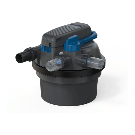
Page 4: Product Description
Product description Overview FCL0007... - Page 5 Water inlet for the pond water being cleaned Connection G2 Opening ring with locking screw for locking the UVC unit head It is necessary to open the opening ring in order to remove the UVC unit head. Water outlet for the cleaned pond water ...
- Page 6 Connection components for installation FCL0012 Hose connector, transparent Use: Water outlet, dirt water outlet Hose connector, black Use: Water inlet Hose connector, black with G2 outer thread Use: Open end of the dirt water hose, the cover cap is screwed onto the outer thread Union nuts G2, for installing the hose connectors Cover cap G2, for closing the dirt water outlet Flat seal for black hose connector and cover cap...
-
Page 7: Function Description
Function description The filter pump pushes the water into the pressure-tight container where it passes through sev- eral cleaning stages before returning into the pond. Cleaning stage “Filtration” The water flows through the foam filters. Mechanical soiling is retained by the foam filters. Sus- pended matter and bio sludge settle on the container bottom. -
Page 8: Symbols On The Unit
Symbols on the unit The unit is dust-proof, fully protected against contact and protected from con- tinuous immersion in water to a depth of 0.1 m. Dangerous UVC radiation Protect the unit from direct sunlight Protect the unit from freezing temperatures Do not dispose of the unit with normal household waste Read the operating instructions Installation and connection... - Page 9 Installing the pressure filter on level ground If you choose not to bury the pressure filter, position it so that it is hidden from sight e.g. cov- ered by bushes. Install the unit near the pond. The ground must be firm and horizontal. FCL0011...
-
Page 10: Establishing The Connections
Establishing the connections Hoses with a diameter of 38 mm or 50 mm can be connected to the pressure filter. The respec- tive hose connectors are part of our scope of delivery. Use hoses with a diameter of 50 mm to keep the pressure losses in the hoses as low as pos- sible. - Page 11 Connecting the dirt outlet The soiled water resulting from cleaning can be used for fertilisation. Connect a hose and route it up to a suitable location (e.g. flower bed). Use a transparent hose connector with a flow lug. The transparent hose connector will allow you to assess the degree of soiling of the water when cleaning the foam filters.
- Page 12 5. Only switch on the UVC clarifier when water emerges from the water outlet. (→ Switching the UVC clarifier on/off) – Never run the UVC clarifier without water flowing through. – If you are using Oase AquaActiv BioKick, leave the UVC clarifier turned off for 24 hours. This allows the starter bacteria to achieve optimum effectiveness.
-
Page 13: Operation
Switching the UVC clarifier on/off Switching on: Plug the power plug into the outlet. – The unit switches on immediately. – The indicator lamp lights up. – The flow lug on the outlet will show you that water is flowing. ... - Page 14 Cleaning the foam filters The Easy Clean function is used to clean the foam filters. During cleaning, the filter pump is switched on so that the dirt water is transported out of the pressure filter. Turn the turning valve to guide the water in the container to the dirt water outlet. This pre- vents the dirt water from flowing back into the pond.
- Page 15 Removing/positioning the filter cover Removing the filter cover How to proceed: Switch off the filter pump and pull the power plug of the UVC clarifier from the outlet. Remove all hoses from the filter cover (unscrew hose connectors). ...
- Page 16 Positioning the filter cover Ensure that the O-ring on the container is positioned correctly on the container rim. – Moisten the seal with water or grease the seal, if necessary, so that the filter head is easier to push onto the container. ...
- Page 17 Cleaning the unit and washing or replacing the foam filters Wear of the foam filters is caused by mechanical stress and normal ageing. Insert new foam filters at the start of the season. Disassembling the foam filter package Prerequisite: ...
- Page 18 Cleaning Clean the container, the clamping ring, the filter cover, the UVC water housing and the meshed tube with a powerful water jet. – Pull off the meshed tube by pulling and simultaneously turning it clockwise. Wash each of the foam filters by forcefully compressing it under running water. –...
- Page 19 Place the closing disc on the final foam filter (purple, 20 ppi). Fasten the closing disc to the two cleaning rods using the two screws. Position the filter cover on the container. (→ Positioning the filter cover) FCL0024 Installation sequence of the foam filters FiltoClear 5000 FiltoClear 13000 FiltoClear 19000 FiltoClear 31000...
- Page 20 Removing/installing the UVC unit head CAUTION The ultra-violet radiation of the UVC lamp can damage your eyes and skin. Never operate the UVC lamp outside out the casing or in a damaged casing. Disconnect the unit from the power grid before starting any maintenance work or before re- ...
-
Page 21: Replacing The Uvc Lamp
Carefully and steadily knock the rotor lid with the quartz glass against a firm surface. The lamp guard will slowly slide out of the quartz glass. OSRAM UVC lamps can only be installed without the holding plate. OASE therefore recom- mends using Philips UVC lamps. - Page 22 FCL0022 Cleaning/replacing the quartz glass The quartz glass is fastened in the filter head by a rotor cover so that no water can leak from the container interior. Replace the quartz glass if it is scratched or has become opaque. Otherwise the cleaning power of the UVC lamp is no longer sufficient.
- Page 23 – Clean the O-ring, replace it if it is damaged. – Grease the O-ring with OASE grease (order number 27872) and pull it over the rim of the quartz glass to avoid grease residue on the quartz glass.
- Page 24 Replacing the cleaning rotor On the FiltoClear 19000 und FiltoClear 31000, an additional cleaning rotor is positioned above the quartz glass to clean the quartz glass with the aid of the water flow. Replace the cleaning rotor when it is worn. Prerequisite: ...
-
Page 25: Wear Parts
Wear parts Foam filters UVC lamp, quartz glass and O-ring for quartz glass Cleaning rotor Replacement clamping screw Pipe connection FiltoClear 19000, 31000 Decommissioning/winter storage Shut down the unit at water temperatures below +8 °C or at the latest when freezing tempera- tures are expected. -
Page 26: Troubleshooting
Troubleshooting Malfunction Possible cause Remedy No water emerges from the water The filter pump is not switched on Switch on the filter pump outlet The supply lines are clogged Check the supply lines and clean them, if necessary The turning valve is not set to “Fil- Turn the turning valve to “Filter ter water”... -
Page 27: Technical Data
Technical data Unit data FiltoClear 5000 13000 19000 31000 UVC clarifier Connection voltage V AC 220–240 220–240 220–240 220–240 Mains frequency 50/60 50/60 50/60 50/60 Power consumption UVC power UVC lamp 18 W 24 W 36 W/42 W 55 W/60 W TC-L(UV-C) TC-L(UV-C) TC-L(UV-C) -
Page 28: Spare Parts
Salt content <0.5 Temperature °C +4 … +35 Spare parts The use of original parts from OASE ensures continued safe and reliable opera- tion of the unit. Please visit our website for spare parts drawings and spare parts. www.oase.com/ersatzteile Disposal NOTE Do not dispose of this unit with household waste. - Page 29 OASE GmbH Tecklenburger Straße 161 48477 Hörstel, Germany +49 (0) 5454 80-0 +49 (0) 5454 80-9353 info@oase.com 77757/10-21...
Need help?
Do you have a question about the FiltoClear 5000 and is the answer not in the manual?
Questions and answers