Table of Contents
Advertisement
Quick Links
Advertisement
Table of Contents

Related Manuals for FY-TECH FY-9000


Summary of Contents for FY-TECH FY-9000
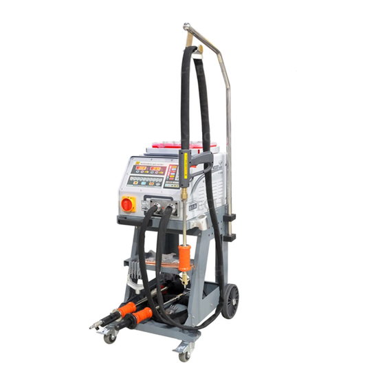
- Page 1 Owner’s Manual FY-9000 The equipment is approved by a number of car manufacturers...
-
Page 2: Table Of Contents
C o n t e n t s 、 Safety Precautions Symbols 、 Symbols and Definitions 、 Accessories and Spare Parts List 、 Installation 1)、 pecifications 2)、Duty ycle and verheating 3)、 achine nstallation 4)、 electing a ocation 5)、 onnecting nput ower 5、... -
Page 3: Safety Precautions Symbols
Safety Precautions Symbols Protect yourself and others from injury, read and follow these precautions before installation and operation. Electric shock can kill: 1、Do not touch live electrical parts。 Re ad in st ru ct io ns . 2、Wear dry,hole-free insulating gloves and 1、Re ad ow ne r' s Ma nua l be fo re using or servicing body protection. -
Page 4: Symbols And Definitions
Definitions S ymbols a n d D e f i n itions Rated maximum 1max supply current Amperes Percent Volts Ma xi mu m ef f e c t i v e 1eff su pp l y cu r r e n t Increase D egr ee of pr o t e c t i o n P r o t e c t i v e ea r t h... -
Page 5: Accessories And Spare Parts List
A c c e s s o r i e s An d S p ar e p ar t s Acc e s s ories a nd S p a re P a r t s L i s t P u l l ha m m e r Ve r t i c a l sp o t we l d i n g Pn e uma t ic v a c uum c u p ule... -
Page 6: Installation
Installation 1、specifications 380V 50/60HZ I n p u t v o l t a g e AC1V-13V Output voltage K r i p t o l h e a t i n g A C 6 V - 1 0 V w a s h e r w e l d i n g A C 1 V - 1 2 V d o u b l e - s i d e w e l d i n g A C 1 V - 1 3 V 22KW... -
Page 7: Overheating
2、Du ty C ycle a nd Overheating Du ty c y cle i s percentage of 10 minutes th at u ni t c an w el d a t ra ted l oad w ithout overheating. Th e we lder is equipped with o ver-h er t p rot ec ti on .On e xc eed in g th e cr iti ca l temperature,the welder w il l b e st opp ed a ut oma ti cl ly .The we lde r can be used again afte r cool in g d ow n. -
Page 8: M Achine I Nstallation
3、Mac hi ne I nstallation 1) Op en t he p ackage a nd f ind out the owner's m a nu al。 2)C he ck t he s upplied o f a ccessories according to packing list t h at a ttached to t his m anu al. 3) Pro pe rly i nstall t his e quipme nt a s following diagram.Inspect t he u nit f or a ny problems.If so,contact your loc al d is tr ib ut or o r s e rvice a gency.To l ocate a d istributor or service ag en cy . -
Page 9: P Ower
4、S el ecting a L ocation 1) Se lect a c orrect l ocation t o p lace the unit 2)D et ermine i nput p ower c ord l e ng th a ccording to its actual o p era tion r equirement . Make s u re t hat the supply cable is a t l e as t 6 mm in diameter 3) Do n ot m ove o r o perate u nit where it could ti p. - Page 10 5、Co nne cting I nput Power 1、Input power cord(n ot less t han 6mm copper co rd). 2、Over-current p rotection. 3、Disconnect dev ice line terminals. 4、Ground wire L1/L2 input c onductors. Installation must meet all National and Local Codes---have only qualified persons make this installation.
-
Page 11: 5、 O Pe R Ation
O p e r ati o n 1、Con trols 1、L C D D i s p l ay 2、T i m e a d ju s tm e nt ( In c re a se ) 3、T i m e a d ju s tm e nt ( De c re as e ) 4、C u r r e n t a d ju s tm en t (I n cr e as e ) 5、C u r r e n t a dj u st m en t (D e cr e as e ) 6、L e f t... -
Page 12: G Un And A Daptors
2、W eld ing G un a nd A daptors 1、Electrode h o lder 2、Trigger Sin g l e - S i d e d appl i c a t i o n s Carbo Rod Shrinking OT Washer Welding Washer Welding Stud Welding Single-sided Welding Wave form Wire Welding... - Page 13 3、O per ation a、spot welding F008+F020 Connect spot welding Set c orrect amperage. Connect negative outside wire electrode tip with welding to a clean,paint-free location gun and tighten. on metal workpiece,as close to welding area as possible. Set correct time. Approximately a 90°angle to the workepiece surface.
-
Page 14: Elding
3、O per ation b、Washer Welding F017+F011+F020 Connect negative outside wire Connect washer adaptor with Set correct amperage. to a clean,paint-free location welding gun and tighten, on metal workpiece,as close to Install washer. welding area as possible. Approximately a 90°angle to the Remove welding gun.Hook the Set correct time. -
Page 15: C、Triangle Asher Elding
3、Operation c、Triangle Washer Welding F003+F020 Se t corr ect am pe rag e. Connect triangel washer Connect negative outside wire pull hammer with welding gun. to a clean,paint-free location on metal workpiece,as close to welding area as possible. Slide the hammer to opposite Approximately a 90°... -
Page 16: D、Carbon Rod Eating
3、Operation d、Carbon rod Heating F007+F009+F020 Set correct amperage. Connect carbon rod and Connect negative outside wire carbon rod adaptor with to a clean,paint-free location welding gun. on metal workpiece,as close to welding area as possible. Use cold water or wet rag Carbon rod turning in Set correct time. -
Page 17: E、 Ave Orm Ire Elding
3、Operation e、 Wri ggle Form Wire Welding F006+F010+020 Connect negative outside wire Connect wriggle wire electrode Set cor rec t amperage. to a clean,paint-free location tip with welding gun. on metal workpiece,as close to welding area as possible. Se t correct t i me . Place a wave form wire horizontally Connect hook puller with pull hammer. -
Page 18: F、 C Upules
3、Operation f、Cupules Manual operating cupule: 1、 onnect manual cupule with pull hammer. 2、 sh ma nua l c upu le in to loc k the cupule on the dent. 3、Slide the hammer to opposite direction to pull the dent out. Pneumatic vacuum cupule: 1、Connect gas/air supply with the adaptor... -
Page 19: Iew
Maintenance 1、Exploded view Resistor Circuit board 继电器 Main power switch 风扇 Control transformer Main transformer Capacitor and small resistor Silicon control Left side view Resistor Control transformer 风扇 Main transformer Right side view P a g e . 1 7... - Page 20 M a i n t e n an ce 2、Troubleshooting Trouble Reason Remedy (1)Connect power supply according (1)Connected power supply to manufacturer’s tructions. No welding output incorrectly. (2) lace power s itch in “on” (2)Power switch in off position. position (1)Replace trigger.
-
Page 21: 7、Electrical Diagram
P a g e . 1 9...
Need help?
Do you have a question about the FY-9000 and is the answer not in the manual?
Questions and answers