
Related Manuals for FY-TECH FY-9000A


Summary of Contents for FY-TECH FY-9000A
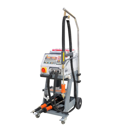
- Page 1 Owner’s Manual FY-9000A The equipment is approved by following car manufacturers ( China)
-
Page 2: Table Of Contents
Contents 、 Safety Precautions Symbols 、 Symbols and Definitions 、 Accessories and Spare Parts List 、 Installation 1)、 pecifications 2)、Duty ycle and verheating 3)、 achine nstallation 4)、 electing a ocation 5)、 onnecting nput ower 5、 Operation 1)、 ontrols 2)、 elding un and daptors 3)、... -
Page 3: Safety Precautions Symbols
Safety Precautions Symbols Protect yourself and others from injury, read and follow these precautions before installation and operation. Electric shock can kill: 1、Do not touch live electrical parts。 Read instructions. 2、Wear dry,hole-free insulating gloves and 1、Read owner's Manual before using or servicing body protection. -
Page 4: Symbols And Definitions
Definitions Symbols and Definitions Rated maximum 1max Amperes supply current Percent Volts Maximum effective 1eff supply current Increase Degree of protection Protective earth Rated welding Line connection (Ground) current Power rating Single phase Do not do this product of voltage Loose shield cup and current(KVA) Suitable for some... -
Page 5: Accessories And Spare Parts List
Accessories And Spare parts Accessories and Spare Parts List Pull hammer Vertical spot welding Pneumatic vacuum cupule pull hammer NO.F003 NO.F002 NO.F001 Wriggle Claw puller Hook NO.F006 NO.F004 NO.F005 Kriptol adaptor Spot welding electrode Carbon Cod NO.F009 NO.F008 NO.F007 Electrode holder Waveform electrode tip Washer adaptor NO.F012... -
Page 6: Installation
Installation 1、specifications Input voltage Single phase 220V 50/60HZ Output voltage Carbon Rod heating AC6V-10V W asher welding AC1V-12V d ouble-side welding AC1V-13V Input power( Instant max.current 5800 Input current(A) Operation way Electronic timer,continuity Time regulation system 0-99ms Operation place Infinity One side welding 1.0+1.2 thickness(mm) -
Page 7: Duty C Ycle And O Verheating
2、Duty Cycle and Overheating Duty cycle is percentage of 10 minutes that unit can weld at rated load without overheating. If unit overheat,output stops ,and cooling fan runs .Wait fif- teen minutes for unit to cool.Reduce amperage or duty cycle be- fore welding. -
Page 8: 3 Machine Installation
3 Machine Installation 1)Open the package and find out the owner s manual 2)Check the details of supplied accessories according to packing list that attached to this manual 3)Properly install this equipment as following diagram Inspect the unit for any problems If so,contact your local distributor or service agency.To locate a distributor or service agency. - Page 9 4、Selecting a Location 1)Select a correct location to place the unit。 2)Determine input power cord length according to its actual o- peration requirement.Input power cord must have a minimum inside diameter of 6mm 。 3)Do not move or operate unit where it could tip。 4)Use cart or unit handle to move unit .Do not pull the cords to move unit.
- Page 10 5、Connecting Input Power The power supply must have a ground connection. The welder must also be connected to circuit breaker. 1、Input power cord(not less than 6mm copper cord). 2、Over-current protection. 3、Disconnect device line terminals. 4、Ground wire L1/L2 input conductors. Power connection and installation must meet all Installation must meet all National and National and Local standards(Circuit breaker must be Local Codes---have only qualified persons...
-
Page 11: P Ower
Operation 1、Controls Operation 1、Time Display 1、Properly make input connections 2、Power Display 2、Turn on the welder.Push the Weld Programs 3、Time--Decrease button to select the desirous weld procedure. 4、Time ---Increase 3、Set Automatic/ Manual.Adjust weld time and 5、Power ---Decrease power. 6、Power----Increase 4、In Manual mode,weld time means the switching 7、Welding Programs time of welder which is controlled by the user.(Note: 8、... -
Page 12: W Elding G Un And A Daptors
2、Welding Gun and Adaptors 1、Electrode holder 2、Trigger Single-Sided applications Carbo Rod Shrinking OT Washer Welding Washer Welding Stud Welding Single-sided Welding Wave form Wire Welding Pulling Spot Hammer Connection of negative wire 5、Tighten up the holder 1、 Weld 2 washers on metal workpiece ,as close to welding area as possible. -
Page 13: A、Spot Welding
3、Operation a、spot welding F008+F020 Set correct power Connect negative outside wire Connect spot welding to a clean,paint-free location ( Position C is recommend) . electrode tip with welding on metal workpiece,as close to gun and tighten. welding area as possible. Set correct time. -
Page 14: B、Washer Welding
3、Operation b、Washer Welding Set correct power F017+F011+F020 ( Position A orB is recommend) . Connect negative outside wire Connect washer adaptor with to a clean,paint-free location welding gun and tighten, on metal workpiece,as close to Install washer. welding area as possible. Approximately a 90°angle to the dent.Put on pressure and press Set Mode switch... -
Page 15: C、Triangle Washer Welding
3、Operation c、Triangle Washer Welding Set correct power F003+F020 Connect negative outside wire ( Position A is recommend) . Connect triangel washer to a clean,paint-free location pull hammer with welding gun. on metal workpiece,as close to welding area as possible. Approximately a 90° angle to Set correct time. -
Page 16: D、Carbon Rod Heating
3、Operation D、Carbon rod Heating Connect negative outside wire Set correct power F007+F009+F020 to a clean,paint-free location Connect carbon rod and ( Position A is recommend) . on metal workpiece,as close to carbon rod adaptor with welding gun. welding area as possible. Set correct time Set Mode switch Turn carbon rod clockwise to heat... -
Page 17: E、 Wriggle Form Wire Welding
3、Operation e、 Wriggle Form Wire Welding F006+F010+020 Set correct power Connect negative outside wire to a clean,paint-free location ( Position A is recommend) . Connect wave form wire electrode on metal workpiece,as close to tip with welding gun. welding area as possible. Place a wave form wire horizontally on the dent. -
Page 18: F、Cupules
3、Operation f、Cupules Manual operating cupule: 1、 onnect manual operating cupule with pull hammer. 2、 sh manual operating cupule in to lock the cupule on the concavity. 3、Slide the hammer to opposite direction to pull the dent out. Pneumatic vacuum cupule: 1、Connect gas/air supply with the adaptor of cupule. -
Page 19: 1、Exploded View
Maintenance 1、Exploded view Resistor Circuit board 继电器 Main power switch 风扇 Control transformer Main transformer Capacitor and small resistor Silicon control Left side view Resistor Control transformer 风扇 Main transformer Right side view Page.17... -
Page 20: 2、Troubleshooting
Maintenance 2、Troubleshooting Trouble Reason Remedy Connect power supply according Connected power supply to manufacturer’s tructions. No weld output incorrectly. (2)P lace power s itch in “on” Power switch in off position. position Replace trigger. Trigger damaged. Connect again or replace if nec- Gun control wire broken.
Need help?
Do you have a question about the FY-9000A and is the answer not in the manual?
Questions and answers