
Related Manuals for FY-TECH FY-7000


Summary of Contents for FY-TECH FY-7000
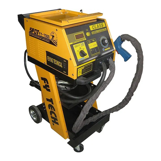
- Page 1 Owner’s Manual FY-7000 The equipment is approved by following car manufacturers (China)
-
Page 2: Table Of Contents
C o nte n t s 、 Safety Precautions Symbol s 、 Symbols and Definition s 、 Accessories and Spare Parts List 、 Installation 1)、 pecifications 2)、Duty ycle and verheating 3)、 achine nstallation 4)、 electing a ocation 5)、 onnecting nput ower 5、... -
Page 3: Safety Precautions Symbols
Safety Precautions Symbols Protect yourself and others from injury, read and follow these precautions before installation and operation. Electric shock can kill: 1、Do not touch live electrical parts。 Re ad in st ru ct io ns . 2、Wear dry,hole-free insulating gloves and 1、Re ad ow ne r' s Ma nua l be fo re using or servicing body protection. -
Page 4: Symbols And Definitions
Symbols and Definitions D e f i n ition s Rated maximum 1max supply current Amperes Percent Ma xi mu m ef f e c t i v e 1eff Volts su pp l y cu r r e n t Increase P r o t e c t i v e ea r t h Rated welding... -
Page 5: Accessories And Spare Parts List
Accessories And Spare parts A c cesso r i e s an d Spare Parts L ist Pull hammer Vertical sp o t we l d i n g Pn e uma t ic v a c uum c u p ule NO.F002 pull ha m m e r NO . -
Page 6: Installation
Installation 1、specifications Model FY-7000 Parameters Single phase Input voltage 220V 50/60Hz Output voltage A C 6 V - 1 0 V C a r b o n r o d h e a t i n g A C 1 V - 1 2 V... -
Page 7: O Verheating
2、D u ty C yc le a nd Overheating D ut y c ycle i s percentage of 10 minutes tha t u n i t c a n w el d a t r at e d l o ad w ithout overheating. Th e w elder i s e qui pp ed with over-h e rt pr o te c t io n .On exceeding the c r it ical t emp er atu re ,the welder will b e s to p p ed au t om a ti c l ly .The w e ld er can b e us ed again after cooling down. -
Page 8: M Achine I Nstallation
3、Ma chi ne I nstallation p en t he p ackage a nd find out the own er's m anual。 2)C hec k t he s upplied a ccessor ies a ccording to packing list t ha t at tached to t his m anual. 3 ) Pro pe rly i n stall t his e quip ment a s following diagram.In sp ect t he u nit f o r a ny problems.If s o,con ta ct y ou r l oc al d is tr ib ut or o r s erv ice a gency.To l ocate a d istributor or service age nc y. -
Page 9: P Ower
4、S el ecting a L ocation 1) Se lect a c orrect l ocation t o p lace the unit 2)D et ermine i nput p ower c ord l e ng th a ccording to its actual o p era tion r equirement . Make s u re t hat the supply cable is a t l ea st 6 mm in diameter 3 )Do n ot m ove o r o perate u nit where it could tip. - Page 10 5、C onn ect ing I nput Power 1、Input power cord(n ot less t han 6mm copper co rd). 2、Over-current p rotection. 3、Disconnect dev ice line terminals. 4、Ground wire L1/L2 input c onductors. Installation must meet all National and Local Codes---have only qualified persons make this installation.
-
Page 11: C Ontrols
O p e rati o n 1、Co ntr ols 1、 Voltmeter 2、 Current adjustment High 3、 Mode 4、 Time adjustment 5、 Power switch 6、 Negative outside wire 7、 Welding gun output cable P a g e . 9... -
Page 12: G Un And A Daptors
2、We ld ing G un a nd A daptors 1、Electrode ho l der 2、Trigger Sin g l e - S i d e d appl i c a t i o n s Carbo Rod Shrinking OT Washer Welding Washer Welding Stud Welding Single-sided Welding Wave form Wire Welding... -
Page 13: Elding
3、Op era ti on 、 a、spot welding F008+F020 Set correct amp erage . Connect negative outside wire Connect spot welding to a clean,paint-free location ( P o s i t i o n C i s r e c o m m e n d ) . electrode tip with welding on metal workpiece,as close to gun and tighten. -
Page 14: Elding
3、Op era ti on b、Washer Welding Set correct amperage. F017+F011+F020 Connect negative outside wire ( P o s i t i o n A o r B i s r e c o m m e n d ) . Connect washer adaptor with to a clean,paint-free location welding gun and tighten,... -
Page 15: Elding
3、Operation c、Triangle Washer Welding Set correct am perage. F003+F020 Connect negative outside wire ( P o s i t i o n A i s r e c o m m e n d ) . to a clean,paint-free location Connect triangel washer pull hammer with welding gun. -
Page 16: H Eating
3、Operation d、Carbon rod Heating Set correct amperage. Connect negative outside wire F007+F009+F020 to a clean,paint-free location Connect carbon rod and on metal workpiece,as close to carbon rod adaptor with ( P o s i t i o n A i s r e c o m m e n d ) . welding area as possible. -
Page 17: Elding
3、Operation e、 Wave Form Wire Welding Se t correct amp era ge. F006+F010+020 Connect negative outside wire to a clean,paint-free location Connect wave form wire electrode ( P o s i t i o n A i s r e c o m m e n d ) . on metal workpiece,as close to tip with welding gun. -
Page 18: F、Cupules
3、Operation f、Cupules Manual operating cupule: 1、 onnect manual cupule with pull hammer. 2、 sh ma nua l c upu le in to loc k the cupule on the dent. 3、Slide the hammer to opposite direction to pull the dent out. Pneumatic vacuum cupule: 1、Connect gas/air supply with the adaptor... -
Page 19: Iew
Maintenance 1、E x pl o ded v iew Voltmeter Current adjustment switch Main transformer A.C.contactor Contiol transformer L e f t s ide vi e w Control circuit board Main transformer Right si d e v iew P a g e . 1 7... - Page 20 Ma i nt e na n ce 2、Troubleshooting Trouble Reason Remedy (1)Connect power supply according (1)Connected power supply to manufacturer’s instructions. No welding output incorrectly. (2) lace power switch in “on” (2)Power switch in "off" position. position (1)Replace trigger. (1)Trigger damaged. (2)Connect again or replace if nec- (2)Gun control wire broken.
-
Page 21: 7、Electrical Diagram
E l e c t r i c a l D i a g r a m Page.19... - Page 22 Page.20...
Need help?
Do you have a question about the FY-7000 and is the answer not in the manual?
Questions and answers