Table of Contents
Advertisement
Quick Links
Advertisement
Table of Contents

Subscribe to Our Youtube Channel
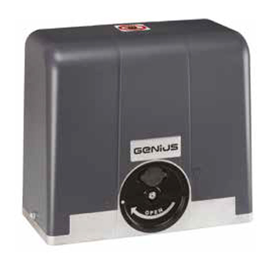
Summary of Contents for Genius BLIZZARD 500
- Page 1 BLIZZARD 500 BLIZZARD 900 Translation of the original instructions...
- Page 2 Müşteriler sadece kendi kullanımları için kopya yoluyla çoğaltma yapabilirler. Bu kılavuz 2018 yılında yayınlanmıştır. Sede legale: FAAC S.p.A. Soc. Unipersonale Via Calari, 10 - 40069 Zola Predosa BOLOGNA - ITALY Tel. +39 051 61724 - Fax +39 051 09 57 820 www.geniusg.com BLIZZARD 500-900 532102 - Rev.B...
-
Page 3: Table Of Contents
3. BLIZZARD 500-900 ........ -
Page 4: Introduction To This Instruction Manual
1. INTRODUCTION TO THIS INSTRUCTION MANUAL This manual provides the correct procedures and requirements for installing BLIZZARD 500-900 and maintaining it in a safe condition. FIGURE E.g.: 1 -3 see Figure 1 - detail 3. When drafting the manual, the results of the risk assessment con- ducted by FAAC S.p.A. -
Page 5: The Manufacturer
4 Symbols: warnings on packaging. regularly check the condition of the components and the packaging. - Storage temperature: 5°C to 30°C. - Percentage of humidity: 30% to 70%. Read the instructions. Handle with care. Fragile parts. BLIZZARD 500-900 532102 - Rev.B... -
Page 6: Unpacking And Handling
One gear motor must be installed for each sliding gate section. The - It is forbidden to use BLIZZARD 500-900 in a constructional gate must be moved via a rack. configuration other than the one provided by the manufacturer. -
Page 7: Emergency Use
Gear motor weight 9.2 kg 9.2 kg 10 kg 10 kg * The ROT technical data refers to the operation with the electronic boards GENIUS SPRINT 382 and SPRINT 383 (maximum ambient tem- perature 20°C). BLIZZARD 500-900 532102 - Rev.B... -
Page 8: Component Identification
2 3.9 DIMENSIONS 6 Components Case and danger symbol Hardware/accessories Electric motor Magnetic limit stop sensor Magnetic limit switches Release device Start-up capacitor Earth connection Z16 Module 4 pinion 4 BLIZZARD 500-900 532102 - Rev.B... -
Page 9: Installation Requirements
Alternatively, apply protective mesh to any such openings. The mesh should be sufficien- tly fine to prevent introduction of body parts requiring protection, in relation to the distance between the fixed and moving parts. BLIZZARD 500-900 532102 - Rev.B... -
Page 10: Example System
4.3 EXAMPLE SYSTEM The example system is a purely illustrative and not exhaustive representation of BLIZZARD 500-900. Mains power supply 3 x 1.5mm Circuit breaker Junction box Blizzard gear motor Photocell TX Photocell RX Key switch Flashing Light 5 5. -
Page 11: Installation Dimensions
5.2 INSTALLATION DIMENSIONS POSITIONING THE BASE PLATE 90° 90° 0-50 0-50 6 7 Opening to the right Opening to the left CENTRELINE DISTANCES ø29 8 POSITIONING THE RACK Foundation 9 Nylon rack BLIZZARD 500-900 532102 - Rev.B... -
Page 12: Base Plate
3. Pass the cables through the supplied cable glands, then insert the cable glands in the holes (13-3). If one of the two holes will not have cables running through it, insert the plastic cable gland whole. BLIZZARD 500-900 532102 - Rev.B... -
Page 13: Manual Operation
Do not weld the rack components to the spacers or to each other. 1. Install the spacers and screws in the upper part of the slots (16-1): This will allow future adjustments if the rail is lowered. 2. Rest the assembled component on the pinion. 16 BLIZZARD 500-900 532102 - Rev.B... - Page 14 10. Add other rack sections until the entire length of the sliding gate section is covered. 11. If the final section is too long, cut it with an angle grinder near one of the slots (19). 17 18 1 9 BLIZZARD 500-900 532102 - Rev.B...
- Page 15 4. Move the leaf forward, checking that the section rests on the pinion. 5. Check the level, then screw in the other two screws, repeating the operations in steps 3 and 4. 2 1 2 2 2 3 BLIZZARD 500-900 532102 - Rev.B...
-
Page 16: Adjustments And Checks
- The rack remains engaged with the pinion along its travel (26-2) - The sliding gate section and gear motor do not touch at any point - There is no friction 2 6 2 7 BLIZZARD 500-900 532102 - Rev.B... -
Page 17: Start-Up
4. Move the gate backwards and fasten the magnet to the rack using the two screws provided (29-1). 30 5. Move the gate to the closed position by hand and make sure that the N.C. contact opens. BLIZZARD 500-900 532102 - Rev.B... -
Page 18: Final Operations
The warranty shall be forfeited in the event of tampering with com- ponents. For replacements, use only original spare parts GENIUS. Before performing any maintenance, disconnect the mains power supply. If the disconnecting switch is not visible, apply a "ATTEN- TION - Maintenance in progress"... -
Page 19: Scheduled Maintenance
Check that the limit switch is intact and that it operates correctly. Control Devices Check that the installed devices and remote controls are in good condition and that they operate correctly. Sensitive Edges Check condition, fastening and correct operation. BLIZZARD 500-900 532102 - Rev.B... -
Page 20: Instructions For Use
During manual operation, gently guide the gate the whole way. Do not push it and let it slide freely. Installations of GENIUS BLIZZARD 500-900 series gear motors must be used for vehicular traffic. Do not leave the gate with the release engaged: after moving it manu- ally, restore automatic operation. - Page 22 Sede legale: FAAC S.p.A. Soc. Unipersonale Via Calari, 10 - 40069 Zola Predosa BOLOGNA - ITALY Tel. +39 051 61724 - Fax +39 051 09 57 820 www.geniusg.com BLIZZARD 500-900 532102 - Rev.B...


Need help?
Do you have a question about the BLIZZARD 500 and is the answer not in the manual?
Questions and answers