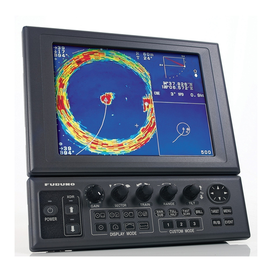
Furuno CH-270 Operator's Manual
Color lcd searchlight sonar
Hide thumbs
Also See for CH-270:
- Important technical installation information (13 pages) ,
- Installation manual (87 pages) ,
- Service manual (89 pages)
Table of Contents
Advertisement
Quick Links
Advertisement
Table of Contents
Troubleshooting

Related Manuals for Furuno CH-270


Summary of Contents for Furuno CH-270
- Page 1 Back OPERATOR'S MANUAL COLOR LCD SEARCHLIGHT SONAR CH-270 MODEL www.furuno.co.jp...
- Page 2 Nishinomiya, 662-8580, JAPAN Telephone : +81-(0)798-65-2111 : +81-(0)798-65-4200 All rights reserved. Printed in Japan Pub. No. OME-13220-D (DAMI ) CH-270 The paper used in this manual is elemental chlorine free. ・FURUNO Authorized Distributor/Dealer A : JUN D : JUN . 03, 2010...
- Page 3 • Store this manual in a convenient place for future reference. • FURUNO will assume no responsibility for the damage caused by improper use or modification of the equipment (including software) by an unauthorized agent or a third party.
- Page 4 Continued use of the equipment can cause fire or electrical shock. Contact a FURUNO agent for service. Do not disassemble or modify the equipment. Fire, electrical shock or serious injury can result.
- Page 5 WARNING LABELS Warning labels are attached to the display, transceiver and hull units. Do not remove the labels. If a label is missing or illegible, contact a FURUNO agent or dealer. Name: Warning Label (1) WARNING Type: 86-003-1011-0 To avoid electrical shock, do not remove cover.
-
Page 6: Table Of Contents
TABLE OF CONTENTS FOREWORD ... vii SYSTEM CONFIGURATION ... ix 1. OPERATIONAL OVERVIEW... 1-1 1.1 Control Description... 1-1 1.2 Remote Controller ... 1-2 1.3 Turning the Power On/Off... 1-3 1.3.1 Power on ... 1-3 1.3.2 Power off ... 1-4 1.4 Raising, Lowering the Transducer ... 1-5 1.4.1 Lowering the transducer ... - Page 7 2.13 Horizontal Menu Overview... 2-23 2.14 Interpreting the Horizontal Display ... 2-25 2.14.1 How the horizontal mode picture is painted ... 2-25 2.14.2 Sample echo displays ... 2-26 2.14.3 Combination display examples... 2-30 3. VERTICAL SCAN MODE ...3-1 3.1 Operational Overview ... 3-1 3.2 Displaying Vertical Scan Mode Display...
- Page 8 5.4.1 Displaying the SYSTEM menu... 5-8 5.4.2 SYSTEM SETTING 1 menu description... 5-9 5.4.3 SYSTEM SETTING 2 menu description...5-11 5.4.4 Sonar (horizontal) mode range settings ...5-13 5.4.5 Vertical scan mode range settings ...5-14 5.4.6 Echo sounder mode range settings...5-15 5.4.7 Track range settings ...5-16 5.4.8 Color palette ...5-17...
-
Page 9: Foreword
Features The CH-270 displays underwater objects on a bright 10.4-inch color LCD display, in 8 (or 16) colors according to received echo strengths. Alternatively, the interface unit permits connection of a commercial CRT or LCD monitor to act as the main, backup or remote display. - Page 10 FOREWORD Usage Precautions • The Motion Sensor MS-100 compensates for ship’s pitching and rolling. However, it does not compensate for load unbalance. Use Clinometer BS-704 if compensation for load unbalance is required. • If the equipment will not be used for a long time, shut off the power to it at the mains switchboard to prevent battery discharge.
-
Page 11: System Configuration
Display Unit External Monitor HULL UNIT SPEAKER Speaker Note 1: The CH-270 is supplied with or without a display unit. For connection of locally supplied monitor, an interface unit is provided. The drawing above shows the system configuration with the MU-100C. - Page 12 External Monitor HULL UNIT DATA/VIDEO OUT SPEAKER Speaker Motion Sensor Note 1: The CH-270 is supplied with or without a display unit. For connection of locally supplied monitor, an interface unit is provided. The drawing above shows the system configuration with the MU-100C.
-
Page 13: Operational Overview
(vertical scan mode). Controls tilt angle. Selects center direction of the vertical scanning sector. Turns target lock on/off. Omnipad Shifts cursor. Selects menu items, options. Opens/closes menu. Inscribes/erases event marker. Inscribes/erases range and bearing markers. * FURUNO monitor only. °... -
Page 14: Remote Controller
1. OPERATIONAL OVERVIEW Remote Controller The Remote Controller CH-256 (option) provides armchair control over range, tilt, target lock and training range. Choose display range. Chooses training range. for full circle 360 ° (horizontal mode) ° or half circle 180 (vertical scan mode). Note: The remote controller can also be used with a commercial monitor. -
Page 15: Turning The Power On/Off
Turning the Power On/Off 1.3.1 Power on Press the [POWER] switch on the control unit until you hear a “click.” A beep sounds, the lamp above the switch lights and the startup display appears (for four seconds). Note 1: Wait at least five seconds before reapplying the power. Note 2: The first time the power is applied after installation, the language selection screen appears. -
Page 16: Power Off
Note 3: The hull unit remains powered when power is turned off at the control unit. Therefore, if the sonar is not to be used for a long period turn it off at ship’s mains switchboard. Transducer status indicator •... -
Page 17: Raising, Lowering The Transducer
Raising, Lowering the Transducer 1.4.1 Lowering the transducer With the boat at the fishing ground, press the [ ] switch to lower the transducer. The lamp above the switch blinks while the transducer is being lowered and lights when it is completely lowered. -
Page 18: Choosing A Display
1. OPERATIONAL OVERVIEW Choosing a Display This sonar has eight display modes and you may choose one with one of the DISPLAY MODE keys. Refer to the chapter shown in the illustration for more information about each mode. HORIZONTAL This mode provides 360 degree coverage. -
Page 19: Adjusting Screen Brilliance, Panel Dimmer
Adjusting Screen Brilliance, Panel Dimmer Screen brilliance can be adjusted in nine levels and the panel dimmer (backlighting) in four. 1. Press the [BRILL] key to open the dialog box for screen brilliance and panel dimmer. Do the next step within four seconds; otherwise the dialog box will be erased. 2. -
Page 20: Basic Menu Operation
1. OPERATIONAL OVERVIEW Basic Menu Operation The menu, consisting of seven menus, mostly contains items which once preset do not require frequent adjustment. Below is the procedure for basic menu operation. 1. Press the [MENU] key to open the menu. The last-used menu is displayed. (In the example below, the COM2 menu is shown.) Note: Either PRESET or SHORT-CUT appears between ES and SYS at the top of the menu depending on the setting of CUSTOM KEY on the SYSTEM SETTING 1... -
Page 21: Horizontal Mode
2. HORIZONTAL MODE Operational Overview The figure below shows the typical horizontal mode operating sequence. 6(a). Set scanning sector. Turn on the power. Adjust gain. Select appropriate Lower the horizontal mode. transducer. Set center bearing of train sector. Set range. 6(b). -
Page 22: Typical Horizontal Mode Display
2. HORIZONTAL MODE Typical Horizontal Mode Display Demonstration mode Cursor data (DEMO) ° B208 Bottom echo Bearing marker Fish echo ETA marker Own ship marker Range marker Event marker Cursor ° B234 Event Ship's marker track* data With the tilt angle lowered, your ship is at the center of the screen. The bottom, which appears in reddish-brown color, is displayed as a circle and fish echoes appear within the circle. -
Page 23: Choosing The Range
Choosing the Range The [RANGE] control chooses the detection (display) range. Choose the range according to either the fish species being searched or the depth desired. 15 ranges are available. BOTTOM BOTTOM Default horizontal mode range settings Range No. Normally, the range is set so that the bottom is traced at the lower part of the screen (like an echo sounder). -
Page 24: Choosing Sector Width
2. HORIZONTAL MODE Choosing Sector Width Sector means the width of the transducer training. The [SECTOR] control chooses the training (display) area among the sixteen positions shown in the table below. Clockwise rotation of the control increases the sector width; counterclockwise rotation decreases it. Sector width (°) -
Page 25: Choosing Train Center
Choosing Train Center The [TRAIN] control chooses the center direction of the detection range. The range of adjustment is 0° to 354° in increments of 6°. The chosen bearing is shown with a filled circle, the train indicator, on the bearing scale. ) →... -
Page 26: Choosing The Tilt Angle
2. HORIZONTAL MODE Choosing the Tilt Angle 2.6.1 Choosing the tilt angle The tilt angle shows the direction to which the sound wave is emitted. When the sound wave is emitted horizontally, the tilt angle is said to be 0° and when emitted vertically, 90°. To set a tilt angle, operate the [TILT] control. -
Page 27: Relation Between Tilt Angle And Echo
2.6.2 Relation between tilt angle and echo Refer to the illustration below to see the relation between tilt angle and bottom echo. Case 1: Tilt angle 30° ° ° ° to 40°: °: °: °: This tilt angle will display the entire bottom since it is captured by the full width of the beam. -
Page 28: Tilt Angle For Surface Fish
2. HORIZONTAL MODE Points to consider • Normally, a vertically distributed fish school is a better sonar target than the bottom, because it reflects the transmitted pulse back toward the transducer. • In case 3, both fish schools “a” and “b” are presented. Generally speaking, however, midwater fish schools tend to be larger than bottom fish schools and they are often displayed near the bottom on the display. -
Page 29: Suitable Tilt Angle
Refer to it to find out the suitable tilt angle for a given depth/detection range. Tilt angle and beam coverage (frequency 180 kHz, vertical beamwidth 8 (200) 20(40) 40(80) 60(120) 80(160) 100(200) 200(400) Vertical width of sonar beam 100 m 14 m 8° (400) (600) 300 m 200 m 28 m Tilt angle and beam coverage 2. -
Page 30: Choosing The Training Speed
2. HORIZONTAL MODE Choosing the Training Speed The training speed determines how fast the transducer scans the sounding sector. Two choices are available, normal speed and high speed, and one may be chosen with the [FAST SCAN] key. Each time the key is pressed, “NORM” (normal speed) or “FAST” (high speed) momentarily appears at the screen top. -
Page 31: Event Marker
Event Marker The event marker functions to mark important locations on the screen, and five may be inscribed. Each time the [EVENT] key is pressed the “latest event marker” ( ) is inscribed at the cursor location and all previously entered event markers are shown by the “previous event marker”... -
Page 32: Deleting All Event Markers
2. HORIZONTAL MODE 2.9.2 Deleting all event markers All event markers can be erased from the screen as follows: 1. Operate the Omnipad to place the cursor outside the display area. 2. Press the [EVENT] key to show the following dialog box. Do the next step within four seconds;... -
Page 33: Adjusting The Picture
2.11 Adjusting the Picture 2.11.1 Suppressing bottom and surface reflections In shallow fishing grounds, excessive sea surface and bottom reflections often interfere with wanted fish echoes and they cannot be eliminated sufficiently with the TVG controls. In such cases, try to reduce the output power, without turning down the gain. The picture becomes clearer when output power is reduced rather than when the gain is decreased. -
Page 34: Suppressing Bottom Tail
The sonar operator will be quite inconvenienced if these echoes are directly displayed on the screen, since he won’t be able to judge the actual size of the target from the size of echoes displayed on the screen. - Page 35 To adjust TVG: 1. Press the [MENU] key to open the menu. 2. Press ▲ to choose MENU and then press ◄ or ► to choose HORZ. MENU COM1 TVG LEVEL TVG DISTANCE GAIN ADJUST RES. COLOR CLUTTER TARGET KEY LOCK MODE AUTO TILT : SELECT...
- Page 36 2. HORIZONTAL MODE 5. Press the [MENU] key to register your selection and close the menu. 6. To suppress reflections from the sea surface or plankton, choose TVG LEVEL and then press ►. TVG LEVEL GAIN 200 m 7. Press ◄ or ► to adjust TVG LEVEL, considering sea conditions. The setting range is 0 to 10, however a setting between 2.0 and 5.0 should provide satisfactory results.
-
Page 37: Erasing Weak Echoes
2.11.4 Erasing weak echoes Weak echoes such as interference can be erased from the screen. This is useful when you want to observe a fish school echo. 1. Press the [MENU] key to open the menu. 2. Press ▲ to choose MENU. 3. -
Page 38: Enlarging Fish Echoes (Horizontal Expansion Display)
2. HORIZONTAL MODE 2.11.5 Enlarging fish echoes (horizontal expansion display) Fish echoes may be enlarged by using the horizontal expansion display. Press the key to show the horizontal expansion display. The direction of expansion depends on the train direction as shown in the table below. Train center direction 318 –... -
Page 39: Target Lock
2.12 Target Lock Three types of target lock modes are available. Manual reverse: The transducer train direction is reserved manually. This is the default target lock function setting and it may be used in both horizontal and vertical scan modes. Position: Tracks stationary position (such as a reef) using position data from a navigator. -
Page 40: Position Mode
2. HORIZONTAL MODE 2.12.3 Position mode This mode tracks a stationary position (such as a reef) using position data fed from a navigator. Note 1: If the [TARGET] key is operated when using the horizontal/vertical scan combination mode, the train angle is automatically pointed toward target direction while the target lock marker is displayed. -
Page 41: Echo Mode
2.12.4 Echo mode The echo mode tracks a fish school, either automatically or manually. The default setting is automatic, and you can choose automatic or manual with “LOCK MODE” in the HORZ menu. Automatic echo tracking mode The automatic echo target lock function automatically tracks a fish school appearing in the operator-chosen target lock area. - Page 42 2. HORIZONTAL MODE When the fish echo is lost the tilt angle is automatically changed as below to continue tracking the echo: Tilt changed to search [(A + 10°) → (A - 10°) →A] Detection area displayed once again and target lock indicator lights.
-
Page 43: Horizontal Menu Overview
2.13 Horizontal Menu Overview This section presents an overview of the items on the HORZ menu. 1. Press the [MENU] key to open the menu. 2. Press ▲ to choose MENU and then press ◄ or ► to choose the HORZ menu. MENU COM1 TVG LEVEL... - Page 44 2. HORIZONTAL MODE CLUTTER: Low intensity echoes, often caused by sediments in water, are painted on the screen as a large number or random dots. This noise can be suppressed. The higher the number (setting) the weaker the echoes which are erased. TARGET KEY: Chooses target lock function among reverse, position and echo.
-
Page 45: Interpreting The Horizontal Display
2. HORIZONTAL MODE 2.14 Interpreting the Horizontal Display This section provides information necessary for interpreting the horizontal display. 2.14.1 How the horizontal mode picture is painted As shown below, the search beam is emitted from the soundome at a certain tilt angle. The information (target echoes) obtained by this beam is displayed in 6°... -
Page 46: Sample Echo Displays
2. HORIZONTAL MODE 2.14.2 Sample echo displays Bottom echoes When the tilt angle is changed, the bottom echo illustrated below will appear on the display. When the tilt is decreased (toward 0°), the bottom trace becomes wider and weaker. By observing the bottom condition on the display, you can prevent damage to the net. -
Page 47: Fish Schools
A fish school appears as a mass of echoes on the screen. The color of the mass shows the density of fish schools on the sonar beam. To find distribution and center point of a fish school, try several different tilt angles. -
Page 48: Sea Surface Reflections
To reduce sea surface reflections, set the tilt angle to 5° or lower, so the upper edge of the sonar beam does not hit the sea surface, or adjust TVG. When a decreased tilt angle is used, sea surface reflections cover a large area as illustrated below. - Page 49 (echo sounder or sonar) on other boats as well as those on own ship. For instance, interference from the sonar on other boats will show itself on the display as in (A) in the figure below. This interference can be suppressed by changing the Tx rate on the COM1 menu.
-
Page 50: Combination Display Examples
2. HORIZONTAL MODE 2.14.3 Combination display examples Horizontal/history display Press the key to display the horizontal/history display. Cursor position data B148 Own ship marker Train position Cursor Horizontal Display (main window) The horizontal display appears in the main window; the history display in the sub window. The length of the picture displayed in the history display is equal to about four full-circle pictures. - Page 51 Target lock indicator Transducer status indicator ° 12. 343' N Position in latitude ° 34. 213' W and longitude* ° Course*, speed* 9.9 kt Sonar range marker (Radius changes with video plotter range.) Event marker (Entered from horizontal mode) Scale Track* 2-31...
- Page 52 2. HORIZONTAL MODE Horizontal/strata display Press the key to display the horizontal/strata display. Cursor position data B133 Own ship marker Train position Color bar for strata display Cursor Horizontal Display (main window) The horizontal display appears in the main window; the strata display in the sub window. The strata picture shows bottom undulations in different colors.
- Page 53 ◆ Color bar for the strata display The depth of the bottom each in all directions is displayed in the sub window, in the colors set by the color bar for the strata display. The color bar for the strata display shows search angle range below 336 degrees.
- Page 54 2. HORIZONTAL MODE ◆ Projection in fore direction and strata display Color "b" Projection in fore direction and strata display ◆ Depth gradually becoming shallower in fore direction and strata display Color "a" Color "a" Depth gradually becoming shallower in fore direction and strata display ◆...
-
Page 55: Vertical Scan Mode
3. VERTICAL SCAN MODE Operational Overview The figure below shows the typical vertical scan mode operating sequence. 7(a). Set scanning sector. Turn on the power. Adjust gain. Lower the transducer. Select appropriate vertical scan mode. Set center bearing of train sector. -
Page 56: Displaying Vertical Scan Mode Display
3. VERTICAL SCAN MODE Displaying Vertical Scan Mode Display 3.2.1 Typical vertical scan mode display Press the key to show the vertical scan mode display. Bearing indicator (Shows training direction.) FORE ship PORT STARBOARD Training indicator (Trained at 190 Interference rejector ON Cursor position... -
Page 57: How The Vertical Scan Picture Is Painted
3.2.2 How the vertical scan picture is painted The sounding beam is emitted and the information (target echoes) obtained by the reflected echo appears in the corresponding sector as it appears on the horizontal mode. The difference is that the training is performed only in vertical direction. It forms a sounding area of a half-circle (like a slice of watermelon) to observe a vertical section of underwater conditions. -
Page 58: Horizontal/Vertical Scan Display
3. VERTICAL SCAN MODE 3.2.3 Horizontal/vertical scan display Press the key to display the horizontal/vertical scan display. Cursor position Vertical scan data bearing cursor ° B156 Own ship marker Train position Cursor Horizontal Display (main window) The size of the vertical scan and horizontal displays and the location of the vertical scan display may be changed as desired. - Page 59 The displays are independent of each other so you can adjust them as desired. Press the [MAIN/SUB] key to choose the window to adjust. Each press of the key momentarily displays MAIN WINDOW CONTROLLABLE or SUB WINDOW CONTROLLABLE at the top of the screen to let you know which window may be adjusted.
-
Page 60: Choosing The Range
3. VERTICAL SCAN MODE Choosing the Range The [RANGE] control chooses the detection (display) range, in 15 settings. Choose the range according to either the fish species being searched or the depth desired. Each time the control is operated the newly chosen range briefly appears in large characters at the screen top. -
Page 61: Choosing Display Sector
Choosing Display Sector Sector means the width of the transducer training, from 6° to 180°. The [SECTOR] control chooses the training area among the sixteen positions shown in the table below. Clockwise rotation of the control increases the sector width; counterclockwise rotation decreases it. -
Page 62: Choosing Sector Center
3. VERTICAL SCAN MODE Choosing Sector Center The center direction of the sounding beam in the vertical direction can be changed with the [TILT] control. The setting range is 0° to 180° in increments of 6°. Choose the setting which places the sector center in the middle of the detection range. Sector center angle set with TILT control PORT... -
Page 63: Choosing The Tilt Speed
Choosing the Tilt Speed The [FAST SCAN] key chooses the tilt speed; that is, the stepping angle at which the transducer scans. Two choices are available, 3 (normal speed) and 6 (high speed). Each time the key is pressed the display momentarily shows “NORM” (normal speed) or “FAST” (high speed). -
Page 64: Event Marker
3. VERTICAL SCAN MODE Event Marker 3.9.1 Entering an event marker The event marker functions to mark important locations on the screen, and five may be inscribed. Each time the [EVENT] key is pressed the “latest event marker” ( at the cursor location and all previously entered event markers are shown by the “previous event marker”... -
Page 65: Deleting All Event Markers
3.9.2 Deleting all event markers All event markers can be erased from the screen as follows: 1. Operate the Omnipad to place the cursor outside the display area. 2. Press the [EVENT] key to show the following dialog box. Do the next step within four seconds;... -
Page 66: Adjusting The Picture
The sonar operator will be quite inconvenienced if these echoes are directly displayed on the screen, since he won’t be able to judge the actual size of the target from the size of echoes displayed on the screen. - Page 67 4. Press ◄ or ► to adjust TVG distance, considering sea conditions. The larger the figure the greater the distance at which the TVG works. Distance Setting Meters Feet Passi/braza Fathoms 2 5. Press ▲ or ▼ to close the dialog box and return to the VERT menu. 6.
-
Page 68: Suppressing Noise And Interference
3. VERTICAL SCAN MODE 3.11.2 Suppressing noise and interference You may encounter occasional or intermittent noise and interference as shown below. This is mostly caused by electrical equipment, engine, propeller noise from own ship, or noise from other sonars being operated nearby. If interference appears, turn on the interference rejector as below to suppress it. -
Page 69: Resolution Color
3.11.4 Resolution color RES. COLOR sets transfer characteristics of input signal level versus display echo level. Echo strength is emphasized in order of CUBE, SQUARE, LINEAR, LOG. You can see the characteristics of each by watching the color bar as you change the setting. 1. -
Page 70: Choosing Horizontal Range Expansion Factor
3. VERTICAL SCAN MODE 3.11.6 Choosing horizontal range expansion factor You may choose the horizontal range expansion factor for the vertical scan picture, from x1 or x2. Note that this feature cannot be adjusted when the vertical search mode, activated by a function key, is turned on. 1. -
Page 71: Interpreting The Vertical Scan Display
3.12 Interpreting the Vertical Scan Display This section provides information necessary for interpreting the vertical scan display. 3.12.1 Sample echo displays Port-starboard picture You can see fish echoes at the center-right of the screen. The bottom is displayed wider as the distance from the ship’s position increases. Therefore, it may be difficult to discriminate bottom fish. - Page 72 Display of net hauling This is an example of net hauling display. The location of the net is indicated clearly. FORE Net hauling and sonar picture False echo In shallow water (depth less than 100 m) detection, unwanted echoes as shown in the figure below may appear.
-
Page 73: Echo Sounder Mode
4. ECHO SOUNDER MODE Operational Overview The figure below shows the typical echo sounder mode operating sequence. Select display sector. Turn on the power. Adjust gain. Lower the transducer. Select echo sounder mode. Set range Set picture advance speed. Control unit Set tilt angle. -
Page 74: Typical Echo Sounder Display
Cursor Range Bottom echo 6.5 m Depth (When the tilt angle is 90 deg., the depth measured by this sonar is displayed inside a rectangle.) Tilt angle indicator Bearing (Shows tilt angle of transducer.) indicator (Shows train Tilt angle direction.) -
Page 75: Choosing The Range
Choosing the Range The [RANGE] control chooses the detection (display) range, in 15 settings. Choose the range according to either the fish species being searched or the depth desired. Each time the control is operated the newly chosen range briefly appears in large characters at the screen top. -
Page 76: Train Direction
4. ECHO SOUNDER MODE Train Direction The sounding beam may be directed 360° in any direction. Operate the [TRAIN] control to choose sounding beam direction. Each setting on the control is an increment of 6°. The train indicator at the top of the screen shows training direction: 0°, fore direction; 90°, starboard direction;... -
Page 77: Measuring Range By Cursor
Measuring Range by Cursor Use the cursor to display the range from own ship to the cursor location. Use the Omnipad to place the cursor where desired. The range to the cursor appears at the upper left-hand corner of the screen. : Range How to measure range with the cursor Event Marker... -
Page 78: Inscribing The Event Marker
4. ECHO SOUNDER MODE 4.8.1 Inscribing the event marker 1. Operate the Omnipad to place the cursor on the location desired for an event marker. 2. Press the [EVENT] key to inscribe the event marker. "Previous event marker" "Latest event marker" How to inscribe and delete the event markers 4.8.2 Deleting all event markers All event markers can be erased from the screen as follows:... -
Page 79: Range Marker
Range Marker The range marker functions to measure the range to a target echo (fish school, bottom, etc.) 1. Operate the Omnipad to place the cursor on the location desired. 2. Press the [R/B] key to display the range marker. The range marker appears along with range indication. -
Page 80: Adjusting The Picture
The sonar operator will be quite inconvenienced if these echoes are directly displayed on the screen, since he won’t be able to judge the actual size of the target from the size of echoes displayed on the screen. - Page 81 3. Press ▲ or ▼ to choose TVG DISTANCE and then press ►. The following dialog box appears. TVG DISTANCE GAIN 200 m 4. Press ◄ or ► to adjust TVG distance. Distance Setting Meters Feet Passi/braza Fathoms 2 5. Press ▲ or ▼ to close the dialog box and return to the ES menu. 6.
-
Page 82: Finding Echo Strength (A-Scope Display)
4. ECHO SOUNDER MODE 4.10.2 Finding echo strength (A-scope display) The A-scope display shows echoes at each transmission with amplitudes and tone proportional to their intensities, on the right 1/4 of the screen. It is useful for estimating the kind of fish school and bottom composition. 1. -
Page 83: Gain Adjustment
4.10.3 Gain adjustment Adjust the gain here when there is disparity in gain level between the main and sub windows. 1. Press the [MENU] key to open the menu. 2. Press ▲ to choose MENU at the top of the screen. 3. -
Page 84: Suppressing Clutter
4. ECHO SOUNDER MODE 4.10.5 Suppressing clutter Low intensity echoes, often caused by sediments in water, are painted on the screen as a large number or random dots. This noise can be suppressed. 1. Press the [MENU] key to open the menu. 2. -
Page 85: Menu Operation
For operation in shallow waters, choose the Tx rate which displays the second reflection from the bottom between the sea surface and bottom. For use of an external video sounder or sonar, choose EXT. INT REJECT: Turns the interference rejector on or off. For further details, see paragraph 3.11.2. -
Page 86: Com2 Menu
5. MENU OPERATION COM2 Menu 5.2.1 Displaying the COM2 menu 1. Press the [MENU] key to open the menu. 2. Press ▲ to choose MENU, and then press ◄ or ► to choose COM2. MENU COM1 DELETING TRACK WHITE MARKER SIG LEVEL COLOR BKGD COLOR... -
Page 87: Short-Cut Menu, Preset Menu
Short-cut Menu, Preset Menu These menus program the CUSTOM MODE keys [1], [2] and [3]. The menu to use may be chosen with CUSTOM KEY on the SYSTEM SETTING 1 menu. Short-cut key: One-touch activation of the operator-selected dialog box. Preset key: One-touch setup of mode, sector, train, range, tilt and scan speed. - Page 88 7. Press ◄ or ► to choose PRESET KEY or SHORT-CUT KEY as desired. 8. Press the [MENU] key twice to register your selection and close the menu. ** SYSTEM MENU ** SYSTEM SETTING: RANGE-SONAR MODE RANGE-VERTICAL MODE RANGE-E/S MODE RANGE-TRACK MODE COLOR PALETTE...
-
Page 89: Changing Setting Of Preset Key
5.3.2 Changing setting of preset key 1. Choose PRESET KEY following the procedure in paragraph 5.3.1. 2. Press the [MENU] key to open the menu. 3. Press ▲ to choose MENU, and then press ◄ or ► to choose PRESET. MENU COM1 MODE... -
Page 90: Changing Setting Of Short-Cut Key
5. MENU OPERATION 5.3.3 Changing setting of short-cut key The default settings are key [1], vertical search; key [2], volume, and key [3], delete track. The operator may change their functions as desired. Note: In the combination modes the short-cut key may only be activated from the main window. -
Page 91: Specifications
Activating a short-cut key 1. Press a CUSTOM MODE key, and the dialog box programmed for the custom key pressed appears. (No dialog box appears for VER. SEARCH.) The dialog box below is for “CLUTTER”. CLUTTER (HORZ): 1 2 3 Note: Vertical search can only be activated when the horizontal mode or a combination mode is active. -
Page 92: System Menu
2. Press ▲ to choose MENU, and then press ► to choose SYS. 3. Press ▼ to choose GO TO SYS MENU. 4. Press ◄ to choose YES. ** SYSTEM MENU ** SYSTEM RANGE-SONAR MODE RANGE-VERTICAL MODE RANGE-E/S MODE RANGE-TRACK MODE COLOR PALETTE... -
Page 93: System Setting 1 Menu Description
5.4.2 SYSTEM SETTING 1 menu description 1. Display the SYSTEM menu and then press ▲ or ▼ to choose SYSTEM SETTING. 2. Press ► to open the SYSTEM SETTING menu. 3. Press ▲ to MENU. 4. Press ◄ to choose “1.” MENU POSITION TRACK... - Page 94 5. MENU OPERATION HEADING INDICATION: Chooses heading indication format, true (figures) or azimuth (compass points, for example, N, S, etc.), for the echo sounder and vertical scan modes. Requires heading data. NORTH MARK: Turns the north marker on or off. Requires heading data. CSE DATA: Chooses heading data source, navigator or gyrocompass, with which to draw ship’s track.
-
Page 95: System Setting 2 Menu Description
5.4.3 SYSTEM SETTING 2 menu description MENU STABILIZER AUTO RETRACTION SPEED ALARM/MESSAGE : SWEEP INDICATOR DEFAULT SETTING MAXIMUM ALLOWABLE SPEED IS 15 KNOTS WHILE SOUNDDOME IS BEING RETRACTED. IF VESSEL HAS RAPID ACCELERATION CAPABILITIES, AUTO RETRACTION SETTINGS OF 10-12 KNOTS ARE MANDATORY TO AVOID CATASTROPHIC DAMAGE TO SOUNDOME ASSY. - Page 96 5. MENU OPERATION SPEED ALARM MESSAGE: Choose the speed at which the speed alarm message is displayed and the aural alarm released when the speed goes higher than that set here. The audio alarm can be silenced with the [R/B] key. [ ] pressed to lower transducer Speed above 15 kts Transducer being lowered...
-
Page 97: Sonar (Horizontal) Mode Range Settings
5.4.4 Sonar (horizontal) mode range settings The user may preset horizontal mode ranges as desired. 1. Choose RANGE-SONAR MODE at the SYS menu and then press ►. DEFAULT SETTING : : SELECT 2. Press ▲ or ▼ to choose range number desired. -
Page 98: Vertical Scan Mode Range Settings
5. MENU OPERATION 5.4.5 Vertical scan mode range settings As with the horizontal mode, the user may preset the vertical scan mode’s ranges. 1. Choose RANGE-VER MODE at the SYS menu and then press ►. DEFAULT SETTING : : SELECT 2. -
Page 99: Echo Sounder Mode Range Settings
5.4.6 Echo sounder mode range settings As with the horizontal and vertical scan modes, the user may preset the echo sounder mode’s ranges. 1. Choose RANGE-E/S MODE at the SYS menu and then press ►. DEFAULT SETTING : : SELECT 2. -
Page 100: Track Range Settings
5. MENU OPERATION 5.4.7 Track range settings You may choose the video plotter display scale range as follows. 1. Choose RANGE-TRACK at the SYS menu and then press ►. DEFAULT SETTING : : SELECT 2. Press ▲ or ▼ to choose range number desired. 3. -
Page 101: Color Palette
5.4.8 Color palette The color palette lets the user change the color of echoes, background, text and menu as desired. Cursor ECHO Arrow BKGD TEXT BKGD1 COLOR : ECHO 1 DEFAULT SET : : SELECT 1. Press ◄ or ► to place the cursor and arrow on the item to change. Pressing ► shifts the arrow and cursor from left to right. -
Page 102: Language
5. MENU OPERATION 5.4.9 Language Menu language can be chosen from among the languages shown in the Language menu. LANGUAGE: : CHANGE MENU: END 5.4.10 System backup System settings can be saved to the internal memory with the menu item SYSTEM BACKUP. -
Page 103: Transducer Frequency Adjustment
5.4.12 Transducer frequency adjustment If the CH-270 is receiving interference from a video sounder or other sonar on board your ship, adjust the frequency of the CH-270’s transducer to reduce the interference. FREQ SHIFT : CHANGE MENU: END 5.4.13 Demonstration mode The demonstration mode provides a simulated sonar picture to help you become acquainted with how your sonar works. -
Page 104: Restoring All Default Settings
5. MENU OPERATION 5.4.14 Restoring all default settings All default menu settings may be restored. Choose YES and then press the [MENU] key to restore all default settings. Note that the settings stored in SYSTEM BACKUP are not disturbed. ARE YOU SURE? NOTE: RESET ALL THE SETTINGS INCLUDED IN SYSTEM MENU TO DEFAULT. -
Page 105: Maintenance, Troubleshooting
6. MAINTENANCE, TROUBLESHOOTING This chapter provides the information necessary for keeping the equipment in good working order. Preventive Maintenance Check the following points monthly. • Check all cables. If damaged, replace. • Check connectors at rear of each unit. Clean if necessary. •... -
Page 106: Hull Unit Maintenance
6. MAINTENANCE, TROUBLESHOOTING Hull Unit Maintenance 6.3.1 Lubrication Coat the raise/lower screw shaft once a year with Molytone grease. Also, grease the raise/lower main shaft (upper part of the grease cotton retainer) twice a year. 6.3.2 Manually raising, lowering transducer Turn off the power at the ship's mains switchboard before conducting the procedure below. -
Page 107: Transducer Maintenance
Hull unit CH-184 1. Turn off the breaker switch on the hull unit. 2. Slightly loosen the bolts fastening the shaft retainer. 3. Raise and lower the shaft by hand to confirm that it raises and lowers smoothly. If it does not rise or lower smoothly, do not use force;... -
Page 108: Troubleshooting
Power cable is too close to the signal cable. Relocate power cable or signal cable. • Debris may be on sea surface. Reject unwanted noise with the interference rejector on the COM1 menu. • Problem in tilt mechanism or control line. Contact a FURUNO agent or dealer for advice. -
Page 109: Error Messages
Error Messages The table below shows the error messages which may appear on the display. All error messages are accompanied by the audio alarm, which you may silence with the [R/B] key. Message Raise/Lower Error RAISE/LOWER FUNCTION HAS NOT BEEN COMPLETED. -
Page 110: Diagnostics
6. MAINTENANCE, TROUBLESHOOTING Diagnostics 1. Press the [MENU] key to open the menu. 2. Press ▲ to choose MENU, and then press ► to choose SYS. 3. Press ▼ to choose GO TO SYS MENU. 4. Press ◄ to choose YES. 5. - Page 111 PANEL programs appear at the top of the display. ROM, RAM, VRAM, NMEA: Checked for proper operation and the results displayed as OK or NG (No Good). For NG contact a FURUNO agent or dealer for advice. TX FREQUENCY: Shows frequency of the transducer.
-
Page 112: Test Pattern
6. MAINTENANCE, TROUBLESHOOTING Test Pattern A test pattern can be displayed to check for proper display of colors. 1. Press the [MENU] key to open the menu. 2. Press ▲ to choose MENU, and then press ► to choose SYS. 3. -
Page 113: Menu Tree
MENU TREE [MENU] key COM1 menu COM2 menu HORZ menu VERT menu ES menu (When SHORT-CUT KEY is selected at SYSTEM SETTING 1 menu.) SHORT-CUT menu PRESET menu (Default setting) (CONTINUED ON NEXT PAGE) TX POWER ( MAX , MIN) PULSELENGTH ( LONG , SHORT) TX RATE (EXTERNAL, 1-10;... - Page 114 MENU TREE (CONTINUED FROM PREVIOUS PAGE) SYSTEM menu SYSTEM SETTING RANGE-SONAR MODE (all default ranges) RANGE-VER MODE (all default ranges) RANGE-E/S MODE (all default ranges) RANGE-TRACK MODE (all default ranges) COLOR PALETTE (Adjusts color of echoes, text and background.) LANGUAGE (JAPANESE, ENGLISH , FRANCAIS, ESPANOL, ITALIANO, PORTUGUES,...
-
Page 115: Specifications
SPECIFICATIONS 1. GENERAL Display System Transmit Frequency Output Power Range (factory settings) Range (m) 1 Horizontal Mode Vertical Scan Mode Output Pulse Length 2. DISPLAY UNIT/ CONTROL UNIT Picture Color Display Mode Combination Display External Data Indication Audio Monitor Event Mark Target Lock (three functions, selected on menu) Scanning Reverse Position Search... - Page 116 SPECIFICATIONS Horizontal Mode Control Range (m) Norm Time (sec) Fast Vertical Scan Mode Control 4. I/O INTERFACE Data Format Input Output 5. POWER SUPPLY Transceiver Unit Hull Unit Rectifier 6. ENVIRONMENTAL CONDITIONS Ambient Temperature Relative Humidity Waterproofing 7. COATING COLOR Display Unit/ Control Unit Transceiver Unit SP-2...
-
Page 117: Index
INDEX AGC ...5-1 A-scope display ...4-10 Auto retraction ...5-11 Auto tilt...2-24 Backup data...5-18 BRILL key ...1-7 Brilliance ...1-7 Clutter echo sounder mode...4-12 horizontal mode ...2-24 vertical scan mode...3-15 Color palette ...5-17 Colors background...5-2 display...5-2 COM1 menu ...5-1 COM2 menu ...5-2 Control description...1-1 Current data...5-9 Custom key... - Page 118 INDEX Menu tree ...AP-1 North mark...5-10 Panel dimmer ...1-7 Picture advance speed (echo sounder mode)...4-4 Position data format...5-9 source ...5-10 POWER switch...1-3 Pulselength...2-14 R/B key echo sounder mode...4-7 horizontal mode ...2-12 vertical scan mode ... 3-11 Range echo sounder mode...4-3 echo sounder mode preset...5-15 horizontal mode ...2-3 horizontal mode preset...5-13...
Need help?
Do you have a question about the CH-270 and is the answer not in the manual?
Questions and answers