Furuno CH-270 Service Manual
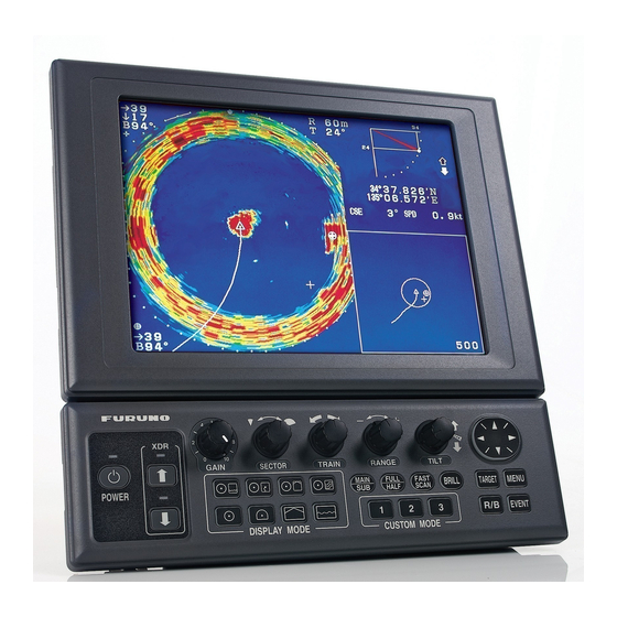
Color searchlight sonar
Hide thumbs
Also See for CH-270:
- Important technical installation information (13 pages) ,
- Operator's manual (118 pages) ,
- Installation manual (87 pages)
Table of Contents
Advertisement
Advertisement
Table of Contents

Subscribe to Our Youtube Channel
Related Manuals for Furuno CH-270


Summary of Contents for Furuno CH-270
- Page 1 COLOR SEARCHLIGHT SONAR CH-270...
- Page 2 *00015124100* *00015124100* *00015124100* *00015124100* ( ( KAOK KAOK ) ) CH-270 CH-270 * 0 0 0 1 5 1 2 4 1 0 0 * * 0 0 0 1 5 1 2 4 1 0 0 * *SME13220A00* *SME13220A00*...
-
Page 3: Table Of Contents
5.4 Tilt Gear Box Replacement................35 5.5 Slip Ring Replacement..................36 5.6 Carbon Brush Replacement ................37 5.7 Tilt Code Disk Alignment................38 TROUBLESHOOTING 6.1 Flow Chart ......................40 Appendix A CH-250 vs CH-270................46 Mechanical Parts List ................... 48 Exploded view ..................... D-1 Schematic Diagram ..................S-1... -
Page 4: System Configuration
CH-273 SPEAKER MOTION SENSOR CONTROL BOX Speaker 12-32 VDC Motion Sensor Note 1: The CH-270 is supplied with or without a display unit. For connection of locally supplied monitor, an 12/24 VDC interface unit is provided. The drawing above shows... - Page 5 CH-273 SPEAKER MOTION SENSOR Speaker 12-32 VDC Motion Sensor 12/24 VDC Note 1: The CH-270 is supplied with or without a display HULL UNIT unit. For connection of CH-181 locally supplied monitor, an interface unit is provided. The drawing above shows the system configuration with the MU-100C.
-
Page 6: Function Of Each Unit
1. FUNCTION OF EACH UNIT 1.1 Display Unit (MU-100C) The Display Unit (MU-100C) consists of DISP board (06P0238), LCD Inverter board, and LCD unit. Figure 1.1 shows the block diagram of Display Unit. DISP Board LCD I/F H-SYNC, V-SYNC, CLK LCD Unit R, G, B, R, G, B,... -
Page 7: Control Unit (Ch)
1.2 Control Unit (CH-252) Figure 1.2 shows the block diagram of the Control Unit. MU100C Figure 1.2 Block Diagram of Control Unit The control unit consists of the control panel and PNL board. The CPU on PNL board reads the settings on the control panel and sends the data to the CPU in transceiver unit through serial data communication bus. -
Page 8: Transceiver Unit (Ch)
1.3 Transceiver Unit (CH-273) The Transceiver Unit consists of CPU board (06P0258), TRX board (06P0241), PWR board (06P0242), and PRA board (06P0259). Major function of CPU board is; 1) To control transmitting and receiving circuits. 2) To generate train/tilt control signal. 3) To generate transducer raising/lowering control signal. - Page 9 1.3.2 TRX Board (06P0241) Figure 1.5 shows the block diagram of TRX board. The TRX board contains a transmission circuit, a receiver circuit, and a audio amplifier circuit. TP10 Loudspeaker Figure 1.3 Block Diagram of TRX Board (06P0241) Transmitter Circuit Transmission carrier signal "TX0/TX1"...
- Page 10 1.3.3 PWR Board (06P0242) Figure 1.6 shows the block diagram of PWR board. The power on/off switch in the control unit generates PSW-H and PSW-L signals to send them to PWR board via the display unit. The PWR board generates 5V, -5V, 12V 12VD, and +B voltage (VTX).
-
Page 11: Pra Board (06P)
1.3.4 PRA Board (06P0259) The preamplifier (PRA) board, 06P0259 locates in the transceiver unit. Figure 1.6 shows the block diagram of PRA board. Trap Circuit Matching From Transmitter To Transducer Transformer Receiving Signal Output Resonance Circuit Pre-Amplifier Figure 1.6 Block Diagram of PRA board... -
Page 12: Functional Description
2. FUNCTIONAL DESCRIPTION 2.1 Transmission Fig. 2.1 shows the signal flow in the transmitter. The TX signal, TX0 and TX1, generated by CPU board (06P0258) is amplified by TRX board (06P0241). The output of the power amplifier is impedance-matched with the transducer with a matching transformer on PRA board (06P0259). - Page 13 Figure 2.1 Signal Flow in Transmitter...
- Page 14 Figure 2.2 Signal Flow in Receiver...
-
Page 15: Raising/Lowering Transducer
2.3 Raising/Lowering Transducer See the simplified circuit diagram below. The CPU generates rising and lower control signals, UPC and DNC. The DNC signal is generated when the down key is pressed and the UPC signal is generated when the up key is pressed. These signals change the status of R/L CONT signal. Lowering Operation The DC motor in the hull unit lowers the transducer, receiving R/L CONT signal from CPU board below. -
Page 16: Tilting Transducer
2.4 Tilting Transducer Fig. 2.4 shows the simplified tilt control circuit. The 4-phase stepping motor is controlled by a phased generator U3 on DRV board. The CPU outputs a clock signal (TIM 1) to the phased pulse generator U3. Receiving the clock signal, the phased pulse generator outputs HIGH level in the sequence shown in Table 2-2, and the motor rotates accordingly. - Page 17 J10 #11 Figure 2.4...
-
Page 18: Training Transducer
2.5 Training Transducer Basically the circuit is the same as the tilt control circuit. See the simplified circuit diagram on the next page. The phased pulse generator U5 drives the train motor with TR CLK (TRM1) and TR CW/CCW (TRM2) signals from CPU board. A slit on the rotary disc generates a “Heading”... - Page 19 J2 #3 J10 #5 Figure 2.5...
-
Page 20: Braking Tilt/Train Motor
2.6 Braking Tilt/Train Motor Fig. 2.6 shows the power supply circuit for the tilt motor. U2 is a retrigger able one-shot multivibrator of which Q output is held “H” while TI CLK is continuously applied to “Ain” pin. Q1 and Q2 are “OFF” and “ON” respectively when TI CLK signal is applied to U2. When TI CLK signal is absent, outputs, Q and Q are held to LOW and HIGH respectively, causing that Q1 goes ON and Q2 OFF. -
Page 21: Check And Adjustment
3. CHECK AND ADJUSTMENT 3.1 Test Points DISP Board (06P0238) Test Points Name Rating Remarks 4.75 to 5.25 V Source voltage of LCD control circuit in LCD 1.unit PGND No name 2.40 V + 0.05 V +12V 11.8 V to 12.2 V Source voltage of LVD inverter board 4.75 V to 5.25 V +5 V for DISP board... - Page 22 Figure 3.1 Output of TRX board Figure 3.2 Output of TRX board (with transducer) (with dummy) PWR Board (06P0242) Test Points Name Rating Remarks VTX-G 0.9 V MOS FET Gate Drive Clock 4.75 to 5.25 V +5 V for CPU and TRX boards TO VTX See figure 3.3 P CLK...
- Page 23 DRV Board (06P0154)
-
Page 24: Led Indication
3.2 LED Indication : ON : OFF : Blink TRX Board (06P0241) Name Status Remarks +B voltage (Green) CR15 Output signal, Blinks at every transmission PWR Board (06P0242) Name Status Remarks +B voltage (Green) IN HL Over voltage or low voltage indicator CR12 Always ON (Green) CR14... - Page 25 3.3 Adjustment Use the proper instrument, otherwise the unit malfunctions. DISP Board (06P0238) Adjusters Measuring Points Measured by Rating Remarks TP12 Frequency 70 kHz ±1 kHz Switching frequency of Counter power circuit Digital 12.1 V9 ±0.1 V Multimeter Digital 2.40 V ±0.05 V LCD Clock Phase Multimeter Adjustment...
- Page 26 3. Unplug J6 and set the output level of the SG to 46 dBuV ( measured by the Volt-meter ). 4. Connect J6 and turn on CH-270. 5. Set the range to 1600 m, Gain to "10", and TVG to "0".
-
Page 27: Parts Location
4. PARTS LOCATION 4.1 Display Unit LCD Display Unit MU100C Control Unit CH-252 Figure 4.1 Display Unit Front View (NMEA) (DATA/VIDEO IN) LCD Inverter DISP Board (CONT) (06P0238) Figure 4.2 Display Unit LCD/PCB Assembly... - Page 28 TP12 R65 ( Freq.) TP 3 ( PGND) F1 ( (12V Adj TP 7 ( +12V) TP10 TP 8 ( +5V) TP1 ( LCD 5V) TP11 (GND) TP 4 ( 2.4V) Figure 4.3 DISP Board (06P0238)
-
Page 29: Control Unit
4.2 Control Unit U5 (CPU) J3 (Factory Use) Figure 4.4 PNL Board (06P0239) 4.3 Transceiver Unit Display unit Speaker 12 to 32VDC Hull unit Motion sensor Figure 4.5 Transceiver Unit (CH-273) - Page 30 TRX Board CPU Board PWR Board (06P0241) (06P0258) (06P0242) PRA Board (06P0259) Figure 4.6 Transceiver Unit (CH-273) Q13 Q12 (VTX) (GND) (Audio) R103 (AUD VOL) TP10 ( Max Gain SPEAKER TP2 (IF) TP8 ( TR1) R70 ( Min Gain) R38 ( GAIN CR15 ( TP9 (...
- Page 31 TP7 (GND) TP1 (TXV) TP3 (TVG) TP2 (SIG) TP5 (TX0) TP6 (TX1) TP4 (KP) TP8 (LCL) R101 R102 TP9 (VOL) TP11 (DISP CLK) CR11 CR12 R86/R87/R88 (from left) CR15 CR17 CR16 TP14 (ROLL) CR18 TP12 (GND) CR41 TP13 (PITCH) TP17 TP16 TP15 TP18 (GND)
- Page 32 TP10 ( TP8 ( To 12V) To 5V) TP4 ( TP9 ( To VTX) To 12VD) CR1 ( VTX) TP1 ( GND) TP12 ( -VIN) R13 ( VTX ADJ) (-VIN) R34 ( +5V ADJ) R29 ( FREQ ADJ) F1 ( 10A) TP2 ( VTX G)
- Page 33 06P0147 TRAIN Board (06P0154) F1 (4A) (12V : 4V / 24V : 3A) Figure 4.11 Raise/Lower Unit...
- Page 34 CR6 to CR9 (from left) Q2 Q3 J3 CR2 CR3 J2 Q4 Q5 Q6 Q7 Q8 Q9 CR16 CR17 Figure 4.12 TRAIN Board (06P0154) Figure 4.13 Raise/Lower Unit...
-
Page 35: Replacement Of Grease Cotton
5. MAINTENANCE 5.1 Replacement of Grease Cotton (Every two years or when water leaks along with the main shaft.) Figure 5.1 5.2 Soundome (D) Replacement Disassembling 1) Place the soundome vertically. 2) Unscrew the soundome (D) fixing screws. 3) Insert screwdrivers with blade width of 7 to 9 mm to the slit on the soundome (D) and rotate them in the opposite directions each other. - Page 36 Assembling 1) Fill the soundome (D) with oil up to the white line on the inner surface. 2) Make sure that the o-ring is in position on the upper dome assembly. 3) Apply the sealant (Kinoruster) to the o-ring. 4) Fit the upper dome assembly into the soundome (D), marking sure that screw holes are aligned.
-
Page 37: Transducer Replacement
5.3 Transducer Replacement Disassembling 1) Remove the transducer support (2 pcs.). 2) Detach the tilt arm assembly from the transducer by unscrewing eight screws. 3) Unsolder transducer lead wires (3 pcs.) Figure 5.4 Assembling 1) Install the transducer with the transducer support (2 pcs.). 2) Screw the tilt pins (2 pcs.) 3) Solder transducer leads wires and fix them as shown in Fig. -
Page 38: Tilt Gear Box Replacement
5.4 Tilt Gear Box Replacement Disassembling 1) Loosen 8 screws and take off the soundome (U). To detach the soundome from the main body, use (-) screwdrivers in the same way as they have been used to remove the soundome (D). -
Page 39: Slip Ring Replacement
5.5 Slip Ring Replacement Disassembling After removing the tilt gear box (see previous section), remove the followings parts until the slip-ring is exposed as shown in Fig. 5.9. 1) Unplug all connectors on pcb 06P0158. 2) Remove the chassis plate (U) assembly, unscrewing four screws. 3) Unscrew two socket set-screws to remove the train gear. -
Page 40: Carbon Brush Replacement
Assembling 1) Clean the slip-ring surface with alchol. 2) Pass the slip-ring assembly through the train shaft and install so that it may be in contact with the base of the train shaft. 3) Solder leads of the slip-ring and apply silicone rubber over them. 4) Loosen the carbon brush fixing screws and install the carbon brush assembly. -
Page 41: Tilt Code Disk Alignment
5.7 Tilt Code Disk Alignment When the tilt gear bos is reinstalled, alignment of the tilt code disk is required. The tilt code disk has three slits; two narrow slits for 30° signal and one wide slit +8° and 93° signals. - Page 42 5) Rotate the tilt code disk so that the second narrowest slit is placed in the center of photo sensor on the tilt signal (1) pcb. See Fig.5.16. Be careful not change the tilt angle of the transducer. Figure 5.16 6) Fix the tilt code disk by tightening the socket set screws.
-
Page 43: Troubleshooting
6. TROUBLESHOOTING 6.1 Flow Chart 1) Train/Tilt Check START Conduct self-check. Conduct results of train/ tilt motor is OK? Measure the supply voltage between J1 #1(+) and #2(-) on PWR board 06P0147. 10.8V to 15.6V for 12VDC set and 21.6V to 31.2V for 24VDC set? Check ship’s supply. - Page 44 Operate the sonar in self-check mode where the display unit alternately drives the tilt/train circuits. Train problem Which is faulty, tilt or train? Tilt problem Check tilt motor drive pulse on DRV board 06P0154. 01 : Q5 (C) Common is (-) of 02 : Q3 (C) ship’s supply.
- Page 45 Check the train motor drive pulse outputs on DRV board 06P0154 . 01 : Q9 (C) +8ms +45V Common is (-) of 02 : Q8 (C) ship’s supply. 03 : Q7 (C) 04 : Q6 (C) Check result is OK? No (Driver circuit is faulty.) Check TR CLK and TR CW/CCW inputs on DRV board 06P0154.
- Page 46 2) Soundome Lowering Check START Press Down arrow key. Down LED blinks and then lights? #2 of J2 on CPU board is High with Down arrow key pressed? CPU board is faulty. Measure the supply voltage between TB1 (+) and (-) in Hull Unit. 10.8V to 15.6V for 12V set and 21.6V to 31.2V for 24VDC set? Check ship’s supply.
- Page 47 3) Soundome Raising Check START Press UP arrow key. Up LED blinks and then lights? #2 of J2 on CPU board is Low DSP board is faulty. Check fuse F1. Problem is cleared by changing F1? Check motor for short circuit. Measure voltage at collector of Q1 on DRV board 06P0154.
- Page 48 4) Transceiver Check Measure TX output signal between TP6 and TP8 on TRX board. Unplug J5 on TRX board and connect the dummy load (100 ohm, 30W) between TP6 and TP8. Measure the TX output again. Slip-ring or Transducer (TX is faulty.) is faulty.
- Page 49 Appendix A CH-250 VS CH-270 Following shows the difference between CH-250 and CH-270 CH-250 CH-270 1) General The transceiver unit and the hull unit are differ from CH-250. The hull unit is the same as CH-18. Load Loudspeaker Loudspeaker Load speaker...
- Page 50 CH-250 CH-270 3) Hull unit control Hull unit UP/DOWN UP/DOWN 4) PRA board Transceiver unit Hull unit Transceiver unit Hull unit Frequency code Frequency code Soumdome Filter Filter Matching Matching Pre-amp trans. Pre-amp trans.
- Page 51 CH- - - - 270 MECHANICAL PARTS LIST 270 MECHANICAL PARTS LIST 270 MECHANICAL PARTS LIST 270 MECHANICAL PARTS LIST Raise/Lower Control, Dwg. No. C1271-E01-A PARTS NAME PARTS NAME TYPE/DWG. NO. TYPE/DWG. NO. CODE NO. CODE NO. PARTS NAME PARTS NAME TYPE/DWG.
- Page 52 PARTS NAME PARTS NAME TYPE/DWG. NO. TYPE/DWG. NO. CODE NO. CODE NO. PARTS NAME PARTS NAME TYPE/DWG. NO. TYPE/DWG. NO. CODE NO. CODE NO. REMARKS REMARKS REMARKS REMARKS TAPERED ROLLER BEARING 30202 000-873-100 C-TYPE CIRCLIP DIA 35 000-866-416 SCREW SHAFT HOUSING 06-013-2224-0 100-099-530 BEARING COLLOR...
- Page 53 Soundome, Dwg. No. C1271-E02-B PARTS NAME PARTS NAME TYPE/DWG. NO. TYPE/DWG. NO. CODE NO. CODE NO. PARTS NAME PARTS NAME TYPE/DWG. NO. TYPE/DWG. NO. CODE NO. CODE NO. REMARKS REMARKS REMARKS REMARKS SOUNDOME (U) 06-013-2101-3 100-098-753 TRANSDUCER ASSEMBLY CH-1812 006-542-330 TRANSDUCER ARM ASSEMBLY CH-1812 006-542-560...
- Page 56 •} ÅÍ Þ¾ ѽ B SCREW ¼ ¬° ¼ ‘g •i M 3•~ 8 NL6448BC33- 31 CHASSI S ASSY. DI SP BOARD ( 000- 881- 404) ( 000- 142- 409) - M U100C ( CH- 250) ( 006- 557- 940) 06P0238 NL6448AC33- 29 ( 000- 143- 337) - M U101C ( FCV- 1200L/ LM )
- Page 57 +ÊÞ² ÝÄÞ SCREW M 4•~ 10 ’± Î ÞÙÄ M 4•~ 10 ( 000- 861- 871) SW •@ W •@ º ȸ ÀÊ߯ · Ý( ÀÞ² ) GASKET 03- 129- 1022 ‘€ •ì ¶ÊÞ° ‘g •i ( 100- 234- 310) CONTROL COVER ASSY.
- Page 58 •} ÅÍ Þ¾ ѽ B ¼ · ز À SCREW PARTI TI ON M 3•~ 8 06- 021- 3802 ( 000- 881- 404) ( 100- 280- 680) ¸ ×ÝÌ ß •} ÅÍ Þ¾ ѽ B CLAM P +ÅÍ ÞSÀ² Ä SCREW CKS- 05- L SCREW...
- Page 59 · ° ¼ ° Ä( J ) •@ 06- 021- 6011 KEY SHEET( J ) ( 100- 279- 870) · ° ¼ ° Ä( E) •@ 06- 021- 6001 KEY SHEET( E) ( 100- 279- 860) · ° į Ì ß Ì...
- Page 60 +ÅÍ ÞSÀ² Ä SCREW 2•~ 4 ( 000- 867- 534) +ÊÞ² ÝÄÞ¾ ѽ F ŠW SCREW LI D M 3•~ 8 06- 021- 5002 ( 000- 881- 960) ( 100- 279- 840) •} ÅÍ Þ¾ ѽ B SCREW ±° ½ ” M 3•~ 8 GROUND PLATE M I F BOARD...
- Page 61 C1322-K07 S-20 Hull Unit General Drawing C1271-023 S-21 Train/Tilt Driver Board C1271-001 S-22 Soundome C1271-036 S-23 IF-8000 Interface Unit 1/2 C1316-K06 S-24 IF-8000 Interface Unit 1/2 C1316-K07 S-25 REM Board (06P0247) C1316-K25 S-26 BS-704 Inclinometer C1259-041 S-27 CH-270 Service Manual...
- Page 62 Takahashi T Takahashi T...
- Page 63 Takahashi T Takahashi T...
Need help?
Do you have a question about the CH-270 and is the answer not in the manual?
Questions and answers