Furuno CH-270 Installation Manual
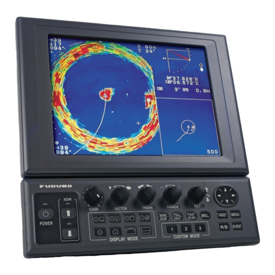
Lcd searchlight sonar
Hide thumbs
Also See for CH-270:
- Important technical installation information (13 pages) ,
- Operator's manual (118 pages) ,
- Service manual (89 pages)
Table of Contents
Advertisement
Quick Links
LCD SEARCHLIGHT SONAR CH-270
SAFETY INSTRUCTIONS ......................... i
SYSTEM CONFIGURATION ................... iii
EQUIPMENT LISTS.................................. v
1. MOUNTING ......................................... 1
1.1 Display Unit, Control Unit ................... 1
considerations ......................... 1
display unit MU-100C .............. 2
monitor..................................... 6
1.2 Transceiver Unit ................................. 7
considerations.......................... 7
1.2.2 Mounting procedure................. 7
1.3 Hull Unit.............................................. 8
considerations.......................... 8
considerations.......................... 8
hull unit ...................................11
1.5 Interface Unit .................................... 24
1.6 Motion Sensor, Clinometer ............... 25
1.6.1 Motion sensor .......................... 25
1.6.2 Clinometer ............................... 26
All brand and product names are trademarks, registered trademarks or service marks of their respective holders.
Installation Manual
2. WIRING.............................................. 27
2.1 Wiring Among Units...........................27
2.2 Transceiver Unit ................................32
2.3 Hull Unit.............................................34
2.5 Interface Unit .....................................36
2.6 I/O Sentences....................................37
3. ADJUSTMENTS ................................ 38
Adjustments.......................................38
Clinometer .........................................42
3.4 System Backup .................................44
3.5 Setting of Interface Unit.....................46
PACKING LISTS
OUTLINE DRAWINGS
INTERCONNECTION DIAGRAMS
www.furuno.co.jp
unit..........................................32
Back
Advertisement
Table of Contents

Related Manuals for Furuno CH-270


Summary of Contents for Furuno CH-270
-
Page 1: Table Of Contents
Back Installation Manual LCD SEARCHLIGHT SONAR CH-270 SAFETY INSTRUCTIONS ......i 2. WIRING..........27 SYSTEM CONFIGURATION ....iii 2.1 Wiring Among Units......27 EQUIPMENT LISTS........v 2.2 Transceiver Unit ........32 2.2.1 Wiring inside the transceiver 1. MOUNTING ......... 1 unit..........32 1.1 Display Unit, Control Unit ....1 2.2.2 Synchronizing transmission with... - Page 2 *00014699713* *00014699713* *00014699713* *00014699713*...
-
Page 3: Safety Instructions
The installer of the equipment is solely Turn off the power at the switchboard responsible for the proper installation of the before beginning the installation. equipment. FURUNO will assume no responsibility for any damage Fire or electrical shock can result if the associated with improper installation. - Page 4 CAUTION CAUTION Observe the following compass safe WORKING WITH THE SONAR OIL distances to prevent deviation of a magnetic compass: Precautions Keep oil away from eyes. Wear protective Standard Steering goggles when working with the oil. The oil can cause inflammation of the eyes. CH-252/ 0.80 m 0.55 m...
-
Page 5: System Configuration
CH-273 SPEAKER MOTION SENSOR Speaker 12-32 VDC Motion Sensor 12/24 VDC Note 1: The CH-270 is supplied with or without a display HULL UNIT unit. For connection of CH-181 locally supplied monitor, an interface unit is provided. The drawing above shows the system configuration with the MU-100C. - Page 6 CH-273 SPEAKER MOTION SENSOR CONTROL BOX Speaker 12-32 VDC Motion Sensor Note 1: The CH-270 is supplied with or without a display unit. For connection of locally supplied monitor, an 12/24 VDC interface unit is provided. The drawing above shows...
-
Page 7: Equipment Lists
EQUIPMENT LISTS Standard supply Name Type Code No. Remarks Control Unit/ System with FURUNO-supplied CH-252/MU-100C — Display Unit monitor Control Unit CH-252 — System with locally supplied monitor Interface Unit IF-8000 — Transceiver Unit CH-273 — CH-181-270 — 350 stroke... - Page 8 Hull Unit (CH-181-270) Specifications Type Cable Shaft Power Stroke Length Length CH-181-1-11-24 2.4 m 1.17 m CH-181-1-11-35 3.5 m CH-181-1-22-35 12 VDC 2.2 m CH-181-1-22-52 5.2 m CH-181-1-38-52 3.8 m 350 mm CH-181-2-11-24 2.4 m 1.17 m CH-181-2-11-35 3.5 m 24 VDC CH-181-2-22-35 2.2 m...
- Page 9 Hull Unit Shipped Configuration (CH-181-270) Name Type Code No. Remarks CH-1811-1 — 12 VDC Raise/Lower 1 set Drive Assy. CH-1811-2 — 24 VDC CH-1812-1-24 — 2.4 m CH-1812-1-35 — 3.5 m 12 VDC CH-1812-1-52 — 5.2 m Train/Tilt Assy. 1 set CH-1812-2-24 —...
- Page 10 Hull Unit Shipped Configuration (CH-184-270) Name Type Code No. Remarks CH-1841-1 — 12 VDC Control Box 1 set CH-1841-2 — 24 VDC CH-1842-1 — Raise/Lower 1 set See Raise/lower drive assy. Drive Assy. CH-1842-2 — CH-1812-1-52 — 5.2 m 12 VDC CH-1812-1-80 —...
- Page 11 000-068-600 06S4086*30m* CP06-01301* Control Unit Cable Type Code No. Remarks MJ-A10SPF0002-0015, For system with CP02-06600* 000-012-486 FURUNO-supplied monitor CP02-06610* 000-012-480 MJ-A10SPF0002-015, 1.5 m Select one, for system with locally CP02-06620* 000-012-481 MJ-A10SPF0002-050, 5 m supplied monitor *: See packing list at back of manual for details.
- Page 12 Option Name Type Code No. Remarks MU-150C — Monitor 1 set MU-100C — Control Unit CH-252 — 1 set Remote Controller CH-256-E — 1 set Interface Unit IF-8000 — 1 set Motion Sensor MS-100 — 1 set Clinometer BS-704 — 1 set Speaker SC-05WR...
-
Page 13: Mounting
1. MOUNTING 1.1 Display Unit, Control Unit This searchlight sonar is available in two configurations: one with the FURUNO-supplied display unit or one with no display unit and an interface unit (with which to connect a monitor, locally supplied). For installation of the system which uses a locally supplied monitor, see paragraph 1.1.3 on page 6 for monitor requirements and installation... -
Page 14: Mounting The Furuno-Supplied Display Unit Mu-100C
1.1.2 Mounting the FURUNO-supplied display unit MU-100C Desktop mounting 1. Fasten the mounting base to the mounting location with four tapping screws. Mounting Base FRONT 2. Do one of the following: ♦ Mounting the display unit and control unit together: 1) Fasten the bracket at the rear of monitor and control units with four binding screws (M4X10). - Page 15 4. Fasten the bracket to the mounting base with two upset screws: Use the upper holes to tilt the display unit 20°; lower holes to tilt it 9°. Use these holes to tilt ° display unit 20 Mounting Base Use these holes to tilt display unit 9 °...
- Page 16 Flush mounting the display unit together with control unit Flush Mount Kit for Display Unit/Control Unit (Type OP06-16, Code no. 006-556-300) Name Type Code No. Remarks Fixing Metal 06-021-1311 100-279-611 Tapping Screw 5X20 000-802-840 Hex. Bolt M4X12 000-882-040 1. Cut out hole (297(H) X 287(W)) in mounting location. 2.
- Page 17 Flush mounting the display unit Flush Mount Kit for Display Unit (Type OP06-17, Code no. 006-556-310) Name Type Code No. Remarks Fixing Metal 06-021-1321 100-279-622 Tapping Screw 5X20 000-802-840 Hex. Bolt M4X12 000-882-040 1. Cut out hole (207(H) X 287(W)) in mounting location. 2.
-
Page 18: System With Locally Supplied Monitor
1.1.3 System with locally supplied monitor Monitor requirements This system requires a standard VGA monitor, connected to the interface unit IF-8000. Supply monitor and interconnection cable locally. A D-sub 15P connector is required for connection to the DATA/VIDEO OUT port on the IF-8000. Use the three rows-type D-sub connector;... -
Page 19: Transceiver Unit
1.2 Transceiver Unit 1.2.1 General mounting considerations • The mounting location should be well ventilated and dry. • The unit can be mounted on a bulkhead or a desktop. For bulkhead mounting, be sure the bulkhead is strong enough to support the weight of the unit under the vibration normally experienced onboard the vessel. -
Page 20: Hull Unit
1.3 Hull Unit 1.3.1 General handling considerations CAUTION Do not turn on the equipment with the transducer exposed to air as this may damage the transducer. The soundome may be painted with antifouling paint to keep marine life of the transducer. Use “Marine Star 20,”... -
Page 21: Mounting The Retraction Tank
1.3.3 Mounting the retraction tank Mounting method Careful attention should be paid to safety (strength, watertightness, etc.) of the tank and also the ease of maintenance and checking. In the off-the-keel installation, it is recommended that the retraction tank protrude through the hull down to 5 cm above the keel for Approx. - Page 22 Installing the retraction tank Install the retraction tank referring to outline drawing for Tank Guide the retraction tank. Note 1: The seam of the tank should be positioned either at the port or starboard side, otherwise the tank guide on the soundome will contact the welded portion of the retraction tank, preventing smooth retraction.
-
Page 23: Assembling And Installation Of Hull Unit
1.3.4 Assembling and installation of hull unit The hull unit is ship disassembled. Follow the procedure below to assemble and install the hull unit. Assembling of soundome 1. Stand the soundome vertically and fill to CAUTION the white line inside the soundome with the sonar oil. - Page 24 4. While pressing down on the upper dome assy., temporarily set two self-locking screws to diagonal holes in the soundome assy. Note that the self-locking screws do not require washers. 5. Fit remaining eight self-locking screws, fastening the screws in diagonal order. This is especially important for the first four screws.
- Page 25 When screw holes are totally out of alignment, detach the soundome as shown below and then reattach it 1. Orient the soundome vertically. 2. Insert two screwdrivers having blade width of 7 to 10 mm in the slits on the soundome as shown below and rotate them in the opposite directions of each other.
- Page 26 Assembling of Hull Unit CH-181-270 (350 mm stroke) BEFORE beginning the installation turn off the breaker inside the hull unit as shown below. Turn it on after completing the installation section. 1. Unfasten six screws to remove the cover from the hull unit. Unfasten six screws: two on top and two on each side.
- Page 27 3. Calculate the length of the main shaft according to tank length “Lt.” Supplied length: 1.17 m (2.2m, 3.8 m) Lt + 170 mm (350 stroke) (Lt = Tank Length) Chamfer edge to Be careful not protect O-ring from to damage. damage.
- Page 28 8. Tighten set screw on lock nut. 9. Using a hammer, bend two sides of lock washer: One side upward Draw BOW mark. onto lock washer and other side downward on main shaft. Bend two sides of lock washer: 10. Mark bow mark on the main shaft One side onto with felt tip pen.
- Page 29 16. Temporarily fix the shaft retainer to the main shaft with two bolts. Screw M10X40 (2 pcs.) Tighten it referring to Note 3 on the Spring Washer Shaft Retainer next page, after completing this procedure. U-nut 17. Place the flange gasket and hull unit on the tank flange and temporarily fix them with bolts and Nut (M16, 2 pcs.)
- Page 30 Note 1: Manual raising and lowering of transducer Remove the top cover of the raise/lower drive assy. and set the hand crank as shown left. Turn off the power switch and disconnect the connector from the motor lead wires on the Hand Crank hull unit before using the hand crank.
- Page 31 Assembling of Hull Unit CH-184-270 (250 mm stroke) See Note 1 on page 22 BEFORE starting the installation. 1. Calculate the length of the main shaft according to tank length “Lt.” Supplied length: 1.17 m (2.2 m) Lt - 17 mm (250 stroke) (Lt = Tank Length) Chamfer edge to Be careful not...
- Page 32 6. Tighten set screw on lock nut. 7. Using a hammer, bend two sides Draw BOW mark. of lock washer: One side upward onto lock washer and other side Bend two sides downward on main shaft. of lock washer: One side onto 8.
- Page 33 14. Temporarily fix the shaft retainer to the main shaft with two bolts. Tighten it referring to Shaft Retainer Note 4 on the next page, after U-nut completing this procedure. Screw M10X40 (2 pcs.) Spring Washer 15. Place the flange gasket and hull unit on the tank flange and Nut (M16, 2 pcs.) Spring Washer...
- Page 34 Note 1: Turn off the breaker switch and cover it with packing tape before starting work on the hull unit. Bodily injury can result if the hull unit is powered while work on it is being performed. Be Turn off breaker sure to turn it on after completing this switch...
-
Page 35: Control Box (For Hull Unit Ch-184)
1.4 Control Box (for Hull Unit CH-184) Install the Control Box close to the hull unit. The length of the connection cable between the Control Box and the soundome assy. is 5.2 or 8 m long and the connection cable from the hull unit is 5 m long. -
Page 36: Interface Unit
1.5 Interface Unit The interface unit is supplied as standard equipment in the system which uses a locally supplied monitor. Mount the unit referring to the outline drawing at the back of this manual and the mounting considerations below. • Choose a location not subject to rain or water splash •... -
Page 37: Motion Sensor, Clinometer
1.6 Motion Sensor, Clinometer 1.6.1 Motion sensor The motion sensor can be installed almost anywhere, taking into account the following mounting considerations. • Choose a place where vibration is minimal. • The ambient temperature of the mounting location should not be more than 50°C (122°F). •... -
Page 38: Clinometer
1.6.2 Clinometer The clinometer detects ship’s inclination caused by ship’s rolling and pitching and its output is used to stabilize the sonar beam against rolling and pitching. The clinometer is, in principle, a pendulum. It measures the inclination of the ship by sensing the direction of gravity acted on it and therefore when installed on a ship, it should be placed on or near the rotation axes of the ship’s rolling and pitching. -
Page 39: Wiring
WIRING 2.1 Wiring Among Units Wire units referring to the drawing on the next several pages. Cables which connect between units have connectors at both ends. Refer to the interconnection diagram at the back of this manual for wiring information. •... - Page 40 Hull Unit CH-181, FURUNO-supplied display unit DISPLAY UNIT Navigator MU-100C Note 1 Note 2 CONTROL UNIT Remote CH-252 Controller (5 m) INTERFACE UNIT Ext. Monitor IF-8000 06S4078 (local supply) (5/10 m) TRANSCEIVER UNIT 12-32VDC HULL UNT DATA/VIDEO OUT CH-273 SPEAKER MOTION SENSOR DPYCYS-1.5...
- Page 41 Hull Unit CH-181, locally supplied monitor INTERFACE UNIT IF-8000 Note 1 Navigation Equipment 15 m External Monitor Note 2 Interface Unit External Monitor 06S4078 (5/10 m) CONT 06S4063 (5 m) 06S4078 (5/10 m) CONTROL UNIT CH-252, (5 m) rear view Remote Controller 12-32VDC...
- Page 42 Hull Unit CH-184, FURUNO-supplied display unit DISPLAY UNIT Navigator MU-100C Note 1 Note 2 CONTROL UNIT Remote CH-252 Controller (5 m) INTERFACE UNIT Ext. Monitor IF-8000 06S4078 (local supply) (5/10 m) TRANSCEIVER UNIT 12-32VDC HULL UNT DATA/VIDEO OUT CH-273 SPEAKER...
- Page 43 Hull Unit CH-184, locally supplied monitor INTERFACE UNIT IF-8000 Note 1 Navigation Equipment 15 m External Monitor Note 2 Interface Unit External Monitor 06S4078 (5/10 m) 64S4063(5 m) CONT 06S4078 (5/10 m) CONTROL UNIT CH-252, (5 m) rear view Remote Controller 12-32VDC HULL UNT...
-
Page 44: Transceiver Unit
2.2 Transceiver Unit 2.2.1 Wiring inside the transceiver unit Detach the cover of the transceiver unit and connect cables as shown in the figure below. Remove the cover of the power terminal board to access connectors on that board. 06P0258 6P NH Connector (local supply) (SHIELD COVER REMOVED) -
Page 45: Synchronizing Transmission With Echo Sounder Or Other Sonar
2.2.2 Synchronizing transmission with echo sounder or other sonar To synchronize transmission of the CH-270 with an echo sounder or other sonar, wire the CH-270 as shown below. Also, see page 40 for how to set up to use external keying pulse. NH6P (local supply) TRANSCEIVER UNIT... -
Page 46: Hull Unit
2.3 Hull Unit Hull unit CH-181 Open the cover of the control box on the hull unit and wire it as shown below. Connect ground wire of cable 06S04046/06S4086 Connect cable from soundome to J2 and J6 Connect cable 06S4086 from transceiver unit to J1 and J5 06P0154 Connect power cable... -
Page 47: Control Box (For Hull Unit Ch-184)
2.4 Control Box (for Hull Unit CH-184) Open the cover of the Control Box and wire it as shown below. Connect ground wire of 06P0154 cable 06S04046/06S4086 Train/Tilt Drive Assy. Connect cable from soundome to J2 and J6 Connect cable 06S4086 from transceiver unit to J1 and J5 Connect cable 06S4054 from raise/lower drive to J3... -
Page 48: Interface Unit
2.5 Interface Unit CONT NMEA DATA/VIDEO IN DATA/VIDEO OUT RGB OUT Transceiver unit cable Navigator monitor Ground 06S4078 Control Connect to ship's body. Monitor unit unit cable cable 06S4078 06S4063 The blackbox-type system (monitor supplied locally) requires a standard VGA monitor, connected to the interface unit IF-8000. -
Page 49: I/O Sentences
Note 5: When connecting the Display Unit MU-100C to the Interface Unit, or two interface units in parallel to the transceiver unit, the length of cables should be as shown below. Note that the length of two cables type 06S4078 cannot exceed 10 m each. External Monitor A+B <... -
Page 50: Adjustments
3. ADJUSTMENTS Turn on the power for the hull unit at the ship’s mains switchboard. Press the [POWER] switch on the control unit. The language selection screen, shown below, appears the first time the power is turned on after completing the installation. English is selected; press the [MENU] key to escape. - Page 51 2. Press the [MENU] key to open the menu. MENU COM1 COM2 HORZ VERT ES PRESET TX POWER PULSELENGTH LONG TX RATE INT REJECT AUDIO LEVEL : CHANGE MENU: END : SELECT 3. Operate the Omnipad to select “SYS” at the far right-hand side of the menu. MENU COM1 COM2...
-
Page 52: Using External Kp (Keying Pulse)
3.2 Using External KP (Keying Pulse) To synchronize transmission of the CH-270 with an echo sounder or other sonar, follow the procedure below. Also, see page 33 for wiring. 1. Press the [MENU] key to open the menu. - Page 53 3.3 Adjusting the Motion Sensor, Clinometer When the ship has a semi-permanent inclination, offset it as below to enable detection of motion by the motion sensor or clinometer. Turn on the CH-270 and wait one minute before setting. 1. Press the [MENU] key to open the menu.
-
Page 54: Adjusting The Motion Sensor, Clinometer
4. Press ◄ to select YES to display the System menu. ** SYSTEM MENU ** SYSTEM SETTING: RANGE-SONAR MODE RANGE-VERTICAL MODE RANGE-E/S MODE RANGE-TRACK MODE COLOR PALETTE LANGUAGE SYSTEM BACKUP LOAD BACKUP DATA HEADING OFFSET, DRAFT OFFSET ADJ MOTION SENSOR TX FREQ ADJUST TEST TEST PATTERN... - Page 55 For Motion Sensor MS-100 Using a clinometer or similar device, measure ship’s semi-permanent inclination angle. Polarity of the values represents ship’s inclination. Take the polarity of the angle as follows: for example, if the stern is 3° down, set -3(°). –...
-
Page 56: System Backup
2. Operate the Omnipad to select “SYS” at the far right-hand side of the menu. MENU COM1 COM2 HORZ VERT ES PRESET GO TO SYS MENU : SELECT MENU: END : CHANGE 3. Press ▼ to choose GO TO SYS MENU. 4. - Page 57 3.5 Setting of Interface Unit When the Display Unit MU-100C is connected to the DATA/VIDEO OUT port on the interface unit, turn OFF all switches on the DIP switch S1. If nothing is connected to the DATA/VIDEO OUT port, turn ON all switches on the DIP switch S1. OFF side *: J6 and J7 should be set for "THROUGH"...
-
Page 58: Setting Of Interface Unit
APPENDIX Retrofitting CH-18/CH-28 This retrofit uses the existing hull unit. A display unit (FURUNO supplied or locally supplied), control unit and transceiver unit are newly installed. Note: The maximum allowable speed with the transducer descended is 15 knots. Please explain this to the owner of the equipment. -
Page 59: Appendix Retrofitting Ch-18/Ch-28
Retrofit for system with FURUNO-supplied display unit Previous Configuration New Configuration Display Unit Display Unit/Control Unit/Transceiver Unit CH-180/CH-280 MU-100C/CH-252/CH-273 Hull Unit↔Display Unit Signal Cable Hull Unit↔Transceiver Unit Signal Cable 06S4047/06S4055 06S4086 Retrofit for system with locally supplied monitor Previous Configuration... - Page 60 Blackbox type Name Type Code No. Remarks Transceiver Unit CH-273 — With SP06-01102 Interface Unit IF-8000 — With SP06-01111 With CP02-06610 (1.5 m cable) CH-252-15 — and FP06-01120 Control Unit With CP02-06620 (5 m cable) CH-252-50 — and FP06-01120 FV2-4, Blue 000-538-118 For transceiver unit 06S4078*10 m*...
- Page 70 Takahashi T Takahashi T...
- Page 71 Takahashi T Takahashi T...
- Page 78 D-10...
- Page 79 D-11...
- Page 80 D-12...
- Page 81 D-13 Takahashi T Takahashi T...
- Page 82 D-14...
- Page 83 D-15...
- Page 84 D-16...
- Page 85 D-17...
- Page 86 Takahashi T Takahashi T...
- Page 87 Takahashi T Takahashi T...
Need help?
Do you have a question about the CH-270 and is the answer not in the manual?
Questions and answers