Table of Contents
Advertisement
INSTALLATION
MANUAL
Models
UATYP60AGXY1
UATYP80AGXY1
UATYP100AGXY1
UATYP120AGXY1
UATYP150AGXY1
UATYP200AGXY1
UATYP250AGXY1
UATYP300AGXY1
UATYP360AGXY1
UATYP420AGXY1
Conditionneurs D'air En Toiture
Kompaktanlage Für Dachmontage
Manuale Di Installazione
Unità A Pacchetto Per Installazione Sul Tetto
Unidades Del Conjunto Del Tejado
Руководство По Установке
Компактные Установки Для Кондиционирования
Воздуха, Монтируемые На Крыше Здания
Çatı Tipi Ambalaj Üniteleri
Installation Manual
English
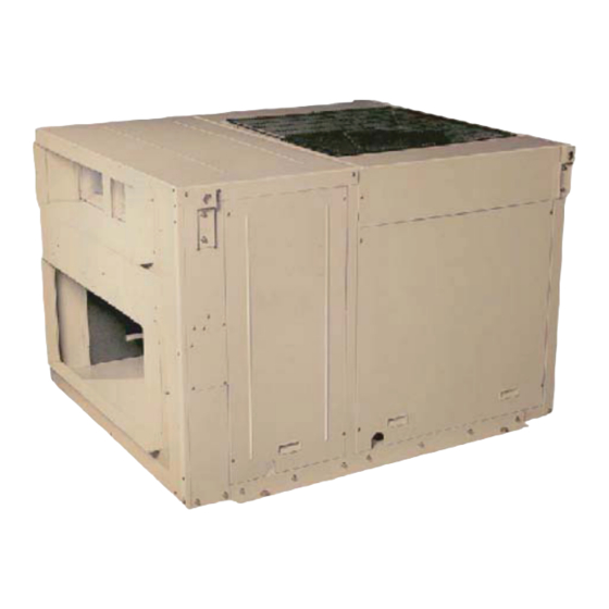
Rooftop Package Units
Manuel D'installation
Français
Installationshandbuch
Deutsch
Italiano
Manual De Instalación
Español
Русский
Kurulum kılavuzu
Türkçe
IM-RTA-0612(5)-DAIKIN
Part No.: R08019037720E
Advertisement
Table of Contents

Related Manuals for Daikin UATYP60AGXY1


Summary of Contents for Daikin UATYP60AGXY1
- Page 1 Rooftop Package Units Manuel D’installation Français Conditionneurs D’air En Toiture Installationshandbuch Deutsch Kompaktanlage Für Dachmontage Models Manuale Di Installazione UATYP60AGXY1 Italiano Unità A Pacchetto Per Installazione Sul Tetto UATYP80AGXY1 UATYP100AGXY1 UATYP120AGXY1 Manual De Instalación Español Unidades Del Conjunto Del Tejado...
-
Page 3: Outline And Dimensions
OUTLINE AND DIMENSIONS UAT(Y)(P)60A (unit ; mm) * Except : Drain size. (unit ; inch) 150 150 150 150 150 150 150 150 Return air duct flange Supply air duct flange 16- ø3 Holes 16- ø3 Holes 4-15X25 Mtg. holes 1000 Detail B Detail A... - Page 4 OUTLINE AND DIMENSIONS UAT(Y)(P)80, 100, 120A (2) Down fl ow Detail B Detail A 140 140 100 100 10 261 View C (Bottom view) 4-15X25 Mtg. holes 16-ø3 Holes 19-ø3 Holes 1000 Hanger (4 places) Drain R 1 Control Condenser Air inlet Wiring hole *(4)RT80,...
- Page 5 OUTLINE AND DIMENSIONS UAT(Y)(P)150, 200A (2) Down flow 140140 59.5 120 120 59.5 Detail A 4-15X25 Mtg. holes 22-ø3 Holes 24-ø3 Holes View C (Bottom view) Hanger (4 places) Detail B Control box Condenser Condenser Condenser Air inlet Air inlet Air inlet Supply air Wiring hole...
- Page 6 OUTLINE AND DIMENSIONS UAT(Y)(P)360, 420A 1730 1130 1800 1080 1220 SUPPLY RETURN 1974 1650 27.5 DETAIL A CENTER OF GRAVITY...
-
Page 7: Safety Precautions
INSTALLATION MANUAL This manual provides the procedures of installation to ensure a safe and good standard of operation for the air conditioner unit. Special adjustment may be necessary to suit local requirements. Before using your air conditioner, please read this instruction manual carefully and keep it for future reference. This appliance is intended to be used by expert or trained users in shops, in light industry and on farms, or for commercial use by lay persons. -
Page 8: Installation Of The Unit
INSTALLATION OF THE UNIT 1.1 Location For Installation Install the unit in such way that air distributed by the unit cannot be drawn in again (as in the case of short circuit of discharge air). Allow suffi cient space for maintenance around the unit. When two or more units are installed in a location, they must be positioned such that one unit will not be taking the discharge air from another unit. -
Page 9: Unit Lifting
INSTALLATION OF THE UNIT 1.4 Unit Lifting UAT(Y)(P)60~200A UAT(Y)(P)250, 300A Hanger brackets at 4 corner of the unit are used for unit lifting purpose. Hanger Bracket Chain The angle A of the chain should be at least 45°, and insulation should be added at 4 corner of the chain to prevent the damage of the panel when lifting. -
Page 10: Space Required Around Units
INSTALLATION OF THE UNIT 1.6 Space required around units (unit ; mm) All space value ; minimum clearance UAT(Y)(P)60, 80, 100, 120A UAT(Y)(P)150, 200A (min clearance) Evaporator coil, Condenser Condenser air fi lter service inlet inlet Condenser Electrical control Evaporator coil, Evaporator coil, inlet circuit &... -
Page 11: Unit Conversion
INSTALLATION OF THE UNIT 1.7 Unit conversion Please check for accessory parts as below. (Packed in the unit, and available for convertible unit only) 1. Side inlet cover 1 piece 2 pieces UAT(Y)(P)80, 100, 120A 2. Casing leg 4 pieces UAT(Y)(P)150, 200A In the case of converting to down fl... -
Page 12: Physical Data
PHYSICAL DATA COOLING ONLY (R22) MODEL UAT60A UAT80A UAT100A UAT120A UAT150A REFRIGERANT REFRIGERANT CHARGE 4.5 x 2 EVAPORATOR AIR FLOW 1800 2826 3532 3600 5651 1334 1667 1699 2667 EXTERNAL STATIC PRESSURE mmAq CONDENSER AIR FLOW 4500 5650 8000 11300 2124 2667 3776... -
Page 13: Electrical Data
ELECTRICAL DATA COOLING ONLY (R22) MODEL UAT60A UAT80A UAT100A UAT120A UAT150A POWER SUPPLY V/ph/Hz 400 / 3N ~ / 50 VOLTAGE RANGE 380 ~ 415 MAX CONTINUOUS CURRENT (COMP) 14.0 23.0 26.9 27.5 23.0 x 2 FULL LOAD CURRENT (FLA, COMP) 12.1 15.6 16.9... -
Page 14: Wire Connection
WIRE CONNECTION • All electrical work must be carried out by qualifi ed electrician and accordance with local supply requirement and associated regulation. Method for connecting electric wire Before connecting the wire, consult the electric power company of jurisdiction. 1. The entire wiring diagram of unit. 2. - Page 15 WIRE CONNECTION Arrangement of terminal block for controller are shown below. CONTROL MODULE UAT(Y)(P)60A CONTROL MODULE UATY(P)150, 200A Connector for remote control UATY(P) only wires 52C1 52C2 52F1 52F2 4 4 W W V V 1 1 4 4 W W V V 2 2 51F1 X1 X2 X3 51F1...
-
Page 16: Over Current
WIRE CONNECTION Wiring Example and Selection of Circuit Breaker 380 ~ 415V, 3N ~ /50 POWER CABLE BREAKER OVER CURRENT EARTH CABLE MODEL CAPACITY (A) PROTECTION SWITCH (A) over) UAT(Y)(P)60A UAT(Y)(P)80A UAT(Y)(P)100A UAT(Y)(P)120A UAT(Y)(P)150A UAT(Y)(P)200A UAT(Y)(P)250A UAT(Y)(P)300A UAT(Y)(P)360A UAT(Y)(P)420A Note: A main switch or other means for disconnection, having a contact separation in all poles, must be incorporated in fi... -
Page 17: Special Precautions When Dealing With R407C Unit
SPECIAL PRECAUTIONS WHEN DEALING WITH R407C UNIT • R407C is a zeotropic refrigerant mixture which has zero • No additional charge of compressor oil is permitted. ozone depletion potential and thus conformed to Montreal • No other refrigerant other than R407C. Protocol regulation. -
Page 18: Vacuuming And Charging
VACUUMING AND CHARGING The rooftop package units are factory pre-charged with suffi cient refrigerant. However, there may be a need for charge recovery during service and maintenance works. Therefore, some precautions must be taken to ensure optimum and trouble-free system operation: (i) The system should be throughly vacuumed to ensure no incompressible gas and moisture in the system. - Page 20 Kita-ku, Osaka, 530-8323 Japan Tokyo offi ce: JR Shinagawa East Bldg., 2-18-1, Konan, P.O.Box 18674, Galleries 4, 11th Floor, Minato-ku, Tokyo, 108-0075 Japan Downtown Jebel Ali, Dubai, UAE. http://www.daikin.com/global/ Importer for Turkey Hürriyet Mahallesi Yakacık D-100 Kuzey Yanyol Caddesi No:49/1-2 Kartal − İstanbul...
- Page 21 Kita-ku, Osaka, 530-8323 Japan Tokyo office: JR Shinagawa East Bldg., 2-18-1, Konan, P.O.Box 18674, Galleries 4, 11th Floor, Minato-ku, Tokyo, 108-0075 Japan Downtown Jebel Ali, Dubai, UAE. http://www.daikin.com/global/ Importer for Turkey Hürriyet Mahallesi Yakacık D-100 Kuzey Yanyol Caddesi No:49/1-2 Kartal − İstanbul...
Need help?
Do you have a question about the UATYP60AGXY1 and is the answer not in the manual?
Questions and answers