Furuno 1715 Service Manual
Hide thumbs
Also See for 1715:
- Operator's manual (48 pages) ,
- User manual (33 pages) ,
- Operator's manual (2 pages)
Table of Contents
Advertisement
Advertisement
Table of Contents

Related Manuals for Furuno 1715


Summary of Contents for Furuno 1715
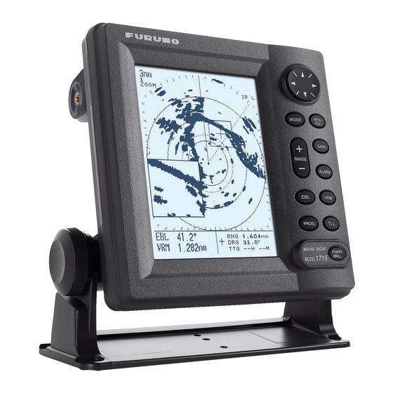
- Page 1 MARINE RADAR MODEL 1715...
- Page 2 Your Local Agent/Dealer Your Local Agent/Dealer 9-52 Ashihara-cho, 9-52 Ashihara-cho, Nishinomiya, Japan Nishinomiya, Japan Telephone : Telephone : 0798-65-2111 0798-65-2111 0798-65-4200 0798-65-4200 FIRST EDITION : FIRST EDITION : SEP. SEP. 2003 2003 Printed in Japan Printed in Japan All rights reserved. All rights reserved.
-
Page 3: Table Of Contents
Contents Chapter 1 Circuit Description 1.1 General...........................1 1.2 Display unit........................2 1.3 Scanner unit ........................6 Chapter 2 Location of Parts 2.1 Display unit........................10 2.2 Scanner unit ........................11 Chapter 3 Adjustment 3.1 Display unit........................13 3.2 Scanner unit ........................13 Chapter 4 Maintenance 4.1 Removing display unit cover ..................14 4.2 Replacement of Major Parts in Display unit..............15 (1) DU board......................15 (2) LCD unit ......................15... - Page 4 Contents Self Test ............................5.3.1 Display unit.....................24 5.3.2 Scanner unit ....................27 5.4 Test points on each board ....................28 1) DU board (03P9320) ...................28 2) MD board (03P9270) ..................28 3) INT board (03P9322) ..................29 4) STC waveform ....................29 Exploded View ................. D-1 Electrical Parts List .................
-
Page 5: Chapter 1 Circuit Description
Chapter 1 Circuit Description 1.1 General The CPUs in the display and scanner units communicate each other via RS-422 interface. The control data, such as Gain, STC and tuning data, is sent from the display unit to the scanner unit in serial. -
Page 6: Display Unit
1.2 Display unit 1.2 Display unit TX trigger pulse is generated by gate array, U79 and sent to the scanner unit. The video signal from the scanner unit is A/D converted and sampled by gate array, U78. Echoes in each sweep are stored on the V-RAM via gate array, U79. - Page 7 1.2 Display unit The display unit consists of PNL board (03P9356), DU board (03P9320) and LCD unit (EW50300FDWR). Each board functions as below. PNL Board (03P9356) This board functions as a man-machine interface, equipped with keys, LEDs for panel-illumination, and a buzzer. DU Board (03P9320) According to the range setting, gate array U79 generates TX trigger pulses in specified pulse repetition rate.
- Page 8 1.2 Display unit Fig.1-3 Block Diagram of DU Board (03P9320)
- Page 9 1.2 Display unit The unit operates on universal voltage ranging from 10.8 V to 31.2 V DC. This range covers the voltage requirement for 12 V/24 V ship’s mains 10 % lower and 30 % higher. The ship’s mains is supplied through a noise filter to the pulsewidth-controlled DC-DC converter which generates the stable voltages;...
-
Page 10: Scanner Unit
1.3 Scanner unit 1.3 Scanner unit In the scanner unit, the TX trigger from the display unit is modulated to use it for triggering the magnetron. The received echo is fed to the MIC and down-converted to 60 MHz IF signal. Auto-gain and auto-STC circuits are not in the scanner unit, but in the display unit. - Page 11 1.3 Scanner unit INT board (03P9322) INT board mainly consists of CPU U4 that includes the RAM, ROM and analog ports, RS-422 interface U5, a motor drive circuit and a gain control signal generator. CPU U4 receives control panel settings on the display unit through the RS422 interface U5. The D/A converter U2 converts Gain, A/C RAIN, and tuning control signals from digital to analog.
- Page 12 1.3 Scanner unit IF Amplifier board (03P9321) The 60 MHz IF amplifier consists of Q1, Q2, U1 and U2, and provides the bandwidth of 7 MHz. The tuning level detector, U3 to U8, detects the main bangs to indicate the tuning level. GAIN CONT signal (From INT Board) Video...
- Page 13 1.3 Scanner unit Trans Reset Fig.1-7 Block Diagram of MD board (03P9270)
-
Page 14: Chapter 2 Location Of Parts
Chapter 2 Location of Parts 2.1 Display unit TP6 (VIDEO) J1351 J1352 TP9 (PWM) TP12 (BUSCLK) (VIDEO OUT) TP15 (RST) TP10 (PWL) TP17 (INV) TP8 (PWS) TP3 (+9V) TP1 (Q6D) TP13 (BP) TP11 (TRIG) TP14 (HD) TP2 (+5V) J7 (RS 232C) TP4 (GND) TP16 (PWR OFF) (EXT BUZZ) -
Page 15: Scanner Unit
2.2 Scanner unit 2.2 Scanner unit J803 J805 J802 J801 J804 Fig.2-2 INT board (03P9322) Fig.2-3 IF board (03P9321) - Page 16 2.2 Scanner unit TP801 VR852 TP807 TP808 TP814 TP805 TP803 TP812 TP806 VR851 VR801 TP811 TP802 (COLD) Fig.2-4 MD board (03P9270)
-
Page 17: Chapter 3 Adjustment
Chapter 3 Adjustment DANGER- High voltage The display unit contains 1 kVAC for LCD backlighting and the scanner unit 300 VDC for TX. 3.1 Display unit +5 V is adjusted by VR1 on DU board. See Fig.3-1 for the location of parts. Table 3-1 Test points of Display unit Item Setting... -
Page 18: Chapter 4 Maintenance
Chapter 4 Maintenance This unit is designed for board level maintenance. Thus, component replacement is not recommended. 4.1 Removing display unit cover To remove the display unit cover: 1. Remove three connector nuts on the display unit cover. 2. Remove six screws fixing the display unit cover to the front panel. 3. -
Page 19: Replacement Of Major Parts In Display Unit
4.2 Replacement of Major Parts in Display unit 4.2 Replacement of Major Parts in Display unit (1) DU board To remove DU board; 1. Disconnect the FPC and the LCD lamp connector. 2. To remove DU board, loosen four screws ringed in Fig.4-3. 3. -
Page 20: Replacement Of Major Parts In Scanner Unit
4.3 Replacement of Major Parts in Scanner unit 4.3 Replacement of Major Parts in Scanner unit Fig.4-6 shows screws which fix boards to the chassis. M4 X 20 M3 X 8 (4Pcs.) Heat sink plate IF board (03P9321) 03-146-3305 M3 X 8 (6 pcs.) M3 X 8 (4 pcs.) MD board (03P9270A) INT board... -
Page 21: Synchronous Belt And Motor
4.4 Synchronous Belt and Motor 4.4 Synchronous Belt and Motor To remove the belt and motor: 1. Unscrew four M3x8 screws marked by *. 2. Remove the radiator assembly. 3. Replace the belt (or motor) with new one. No belt tension adjustment is necessary. 4. -
Page 22: Magnetron
4.5 Magnetron 4.5 Magnetron When handling the magnetron, taking the followings into account not to damage the magnetron physically and electrically. 1) Use a non-magnetic screw driver to dismount and mount the magnetron. 2) Keep the magnetron 25 mm away from the metals. 3) Never pull the magnetron lead wires. -
Page 23: Program Updating
4.7 Program updating 4.7 Program updating The program is upgraded by connecting a PC directly or through a RS232C-RS422 converter. 1. Direct connection of PC 1) Connection The cover of the display unit is removed for the connection of the PC. M O D EL1623 MODEL1715 DU Board (03P9320) - Page 24 XXXX:Ver.No. Run “up1715.bat”. uppg load1715.bin · · · Program upload utility Version 7.05 Copyright(c) FURUNO ELECTRIC · · · · · · Port no. = 1 New wait time:150ms TARGET POWER ON. Turn on the radar.
- Page 25 1) Connection The PC is connected to the NMEA port on the rear panel of the display unit. See Fig.4-11. RS232C-RS422 converter M O D EL1623 MODEL 1715 J1352 R S422 PO R T (N M EA) R S422 TX _H...
-
Page 26: Chapter 5 Troubleshooting
Chapter 5 Troubleshooting 5.1 Error Messages The following messages appear to call the operator’s attention to missing heading or bearing pulses. Check the antenna cable for damage or discontinuity when these messages appear. Table 5-1 Error Messages Message Meaning NO HEADING PULSE Heading pulse is not applied to the CPU on the DU board. - Page 27 5.2 Troubleshooting Matrix table...
-
Page 28: Self Test
5.3 Self Test 5.3 Self Test The self test is performed by following steps below. 5.3.1 Display unit To test the display unit: 1. Turn on the power while pressing and holding down the [MENU/ESC] key to show the Installation menu. INSTALLATION MENU ►... - Page 29 5.3 Self Test NMEA Test result OK: All input is good. --: All input is no good. 01: NMEA1 (input from J1352#3 and #4) is no good or jumper wires are not connected. 02: NMEA2 (input from J1352#1 and #2) is no good. 03: The scanner communication with scanner unit is no good.
- Page 30 5.3 Self Test LCD test 1. Press ▼ to choose LCD PATTERN test. 2. Press ► to start the test. The entire screen is black. 3. Press [MENU/ESC] and the screen turns white. 4. Press [MENU/ESC] again and the screen shows a four-tone display. 5.
-
Page 31: Scanner Unit
5.3 Self Test 5.3.2 Scanner unit Follow the procedure below to test the scanner unit. 1. Press [MENU/ESC] to open the fourth page of the user menu. ▲ ▲ ► RADAR SETUP SCANNER TEST … ▼ (4/4) [MENU/ESC]: Exit. Fig.5-4 4/4 of user menu 2. -
Page 32: Test Points On Each Board
5.4 Test points on each board 5.4 Test points on each board 1) DU board (03P9320) Test point Check Item Ratings Remarks TP1 (TP4) Q6-D 21.7 to 29.4 us Switching Waveform TP2 (TP4) +5 V 4.8 to 5.2 Vdc Adjuster: VR1 TP3 (TP4) +9 V 8.7 to 9.9 Vdc... -
Page 33: Int Board (03P9322)
5.4 Test points on each board 3) INT board (03P9322) Test point Check Item Ratings Remarks A/C RAIN 3.5 to 5.5 Vdc A/C SEA 0 to 4.5 Vdc CNTR 1 Not used GAIN 5.3 to 8.5 Vdc GAIN CONT Same wave as STC 4) STC waveform Condition;... - Page 34 5.4 Test points on each board TP811 (TRIG.) Vp-p=10 V PW=8.0 µS @TX-LONG Setting on oscilloscope 2.00 V, 10.0 µs Waveform 1 TP807 (GATE2) Vp-p=10 V f=38 kHz @ power supply: 24 V Setting on oscilloscope 2.00V, 10.0µs Waveform 2 TP808 (VD2) Vp-p=25 V f=38 kHz...
- Page 35 5.4 Test points on each board TP813 (TX.PW.) Vp-p=10 V PW=1.0 µS @TX-LONG Setting on oscilloscope 2.00 V, 1.00 µs Waveform 4 TP814 (GATE1) Vp-p=8 V f=40 kHz @ power supply: 24 V Setting on oscilloscope 2.00 V, 10.0 µs Waveform 5 03P9269 TP602 (ECHO)
- Page 36 S - 1...
Need help?
Do you have a question about the 1715 and is the answer not in the manual?
Questions and answers