Table of Contents
Advertisement
Quick Links
Installation, Operation, and Maintenance
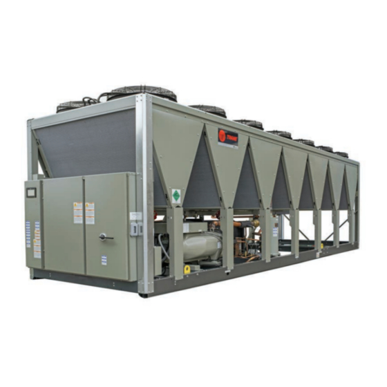
Sintesis™ Air-Cooled Chillers
Model RTAF
Only qualified personnel should install and service the equipment. The installation, starting up, and servicing of
heating, ventilating, and air-conditioning equipment can be hazardous and requires specific knowledge and training.
Improperly installed, adjusted or altered equipment by an unqualified person could result in death or serious injury.
When working on the equipment, observe all precautions in the literature and on the tags, stickers, and labels that are
attached to the equipment.
April 2022
SAFETY WARNING
RTAF-SVX001K-EN
Sintesis™ chillers are part of the Ingersoll Rand EcoWise™ portfolio
of products that are designed to lower the environmental impact
with next-generation, low global warming potential (GWP)
refrigerants and high efficiency operation.
Advertisement
Table of Contents

Related Manuals for Trane RTAF-SVX001K-EN


Summary of Contents for Trane RTAF-SVX001K-EN
- Page 1 Improperly installed, adjusted or altered equipment by an unqualified person could result in death or serious injury. When working on the equipment, observe all precautions in the literature and on the tags, stickers, and labels that are attached to the equipment. RTAF-SVX001K-EN April 2022...
- Page 2 Practices requirements for arc flash protection, PRIOR to servicing the unit. NEVER PERFORM ANY Trane believes that responsible refrigerant practices are SWITCHING, DISCONNECTING, OR VOLTAGE important to the environment, our customers, and the air conditioning industry. All technicians who handle TESTING WITHOUT PROPER ELECTRICAL PPE AND ARC FLASH CLOTHING.
- Page 3 Copyright This document and the information in it are the property of Trane, and may not be used or reproduced in whole or in part without written permission. Trane reserves the right to revise this publication at any time, and to make changes to its content without obligation to notify any person of such revision or change.
-
Page 4: Table Of Contents
AFD Drive Installation ....50 Unit Isolation and Leveling ... 21 Communication Interfaces ....52 Chilled Water Piping Recommendations . 28 RTAF-SVX001K-EN... - Page 5 Satisfied Setpoint ....66 Unloading Unstaging ....67 RTAF-SVX001K-EN...
-
Page 6: Nameplate Information
Identifies unit electrical requirements. • Compressor model number. See Model Number • Lists correct operating charges of R-134a and Description chapter. refrigerant oil (Trane OIL00311). • Compressor serial number. See Model Number • Lists unit test pressures. Description chapter. •... -
Page 7: Model Number Descriptions
No Convenience Outlet Digit 9 — Manufacturing (45 cm/s) 15A 115V Convenience Outlet Location Digit 22 — Insulation Digit 32 — Remote Trane Commercial Systems, Factory Insulation Communication Option Pueblo, CO USA All Cold Parts 0.75” None Evaporator-only Insulation for Digits 10, 11 —... -
Page 8: Compressor Model Number
065 = M3 50Hz 077 = M3 60Hz 077 = M4 50Hz 092 = M4 60Hz 093 = N3/N5 50Hz 112 = N3/N5 60Hz 112 = N6 50Hz 134 = N6 60Hz Digit 16 — Volume Ratio High Volume Ratio RTAF-SVX001K-EN... -
Page 9: General Information
Chilled water inlet and outlet openings are covered for inside the control panel and/or starter panel for shipment. shipment. The Sintesis RTAF features Trane’s exclusive Adaptive Control™ logic, which monitors the control If optional elastomeric isolators are ordered with the unit variables that govern the operation of the chiller unit. -
Page 10: Condenser Fans
3M20 3M22 4M22 4M20 4M18 4M16 4M14 4M12 450T, 500T, 520T 3M11 3M13 3M15 3M17 3M19 3M21 3M23 4M23 4M21 4M19 4M17 4M15 4M13 4M11 3M12 3M14 3M16 3M18 3M20 3M22 3M24 4M24 4M22 4M20 4M18 4M16 4M14 4M12 RTAF-SVX001K-EN... -
Page 11: General Data
99.0 96.3 (ckt 1/ckt 2) 39.2/38.5 39.3/38.5 46.0/44.9 50.4/44.9 49.5/43.7 60.9/58.7 61.1/59.0 Trane OIL00311 (bulk)/OIL00315 (1 gal)/OIL00317 (5 gal) 1.53 1.56 1.56 1.56 1.64 1.96 2.01 Oil Charge/ckt (a) Nominal tonnage at 60 Hz. (b) Minimum and maximum flow rates apply to constant-flow chilled water system running at AHRI conditions, without freeze inhibitors added to the water loop. - Page 12 154.8 118.4 120.0 121.2 259.7 278.8 287.8 (ckt 1/ckt 2) 70.7/70.4 70.7/70.4 119.6/53.8 123.8/54.5 125.4/55.1 115.0/118.0 121.3/126.7 125.0/130.8 Trane OIL00315 (1 gal)/OIL00317 (5 gal) 2.35/2.35 2.35/2.35 4.24/2.17 4.26/2.17 4.27/2.17 4.26/4.29 4.30/4.33 4.33/4.37 Oil Charge (ckt 1/ckt 2) 8.9/8.9 8.9/8.9 16.1/8.2 16.1/8.2...
-
Page 13: Free-Cooling System
It is not advised to dilute a stronger concentrate due to inhibitor dilution. Glycol fluid should be free from foreign solid particles. A maintenance schedule should be selected per the glycol manufacturer’s requirements to insure adequate protection during product usage. RTAF-SVX001K-EN... -
Page 14: Pre-Installation
“unit damage” notation on the carrier’s delivery receipt. Specify the extent and type of damage found and notify the appropriate Trane Sales Office. Do not proceed with installation of a damaged unit without sales office approval. -
Page 15: Installation Requirements
(a) Start-up must be performed by Trane or an agent of Trane specifically authorized to perform start-up and warranty of Trane products. Contractor shall provide Trane (or an agent of Trane specifically authorized to perform start-up) with notice of the scheduled start-up at least two weeks prior to the scheduled start-up. -
Page 16: Dimensions And Weights
4. A full 36” (914 mm) clearance is required in front of the control panels. Must be measured from front of panel, not end of unit base. 5. Clearances shown are sufficient for tube pull. RTAF-SVX001K-EN... -
Page 17: Weights
5767 13642 6188 13109 5946 14039 6368 13039 5915 13986 6344 13435 6094 14381 6523 14457 6558 15483 7023 14870 6745 15897 7211 19509 8849 21313 9668 20027 9084 21819 9897 20294 9205 22192 10066 21519 9761 23404 10616 RTAF-SVX001K-EN... -
Page 18: Option Weights
Note: Weights below for each listed option are in addition to base weights shown in table above. Table 7. Weights — options Windload Option Louver Option Single Point Power Option Unit Size (tons) (a) Model number digit 36 = D. (b) Model number digit 37 = A. (c) Model number digit 28 = 1. RTAF-SVX001K-EN... -
Page 19: Installation Mechanical
Once in place, the unit must be level within 1/2 in (12.7mm) Proper Lifting Configuration Required! across the length and width of the unit. The Trane Failure to follow instructions below could cause the Company is not responsible for equipment problems... - Page 20 Lifting Location 5 (Lifting location 6 located on other side of unit) Lifting Location 3 (Lifting location 4 located on other side of unit) Control Lifting Location 1 Panel (Lifting location 2 Circuit 1 located on other side of unit) RTAF-SVX001K-EN...
-
Page 21: Isolation And Sound Emission
4. Level the unit carefully. Fully tighten the isolator mounting bolts. (Washers under support structure recommended if job site has an I-beam or C-channel.) Table 9. Seismically rated elastomeric isolation pad Dimension (in) Model Max Load Length Width Height B-36 2520 0.625 RTAF-SVX001K-EN... - Page 22 8228 11226 11324 13726 13923 500/520 1529 1018 3609 3278 5679 6078 8500 8228 11226 11324 13726 13923 (a) Dimensions are referenced from end of the unit on the circuit 1 control panel side (not including control panel itself). RTAF-SVX001K-EN...
- Page 23 1969 2139 1967 2135 1963 2132 1958 2126 1954 2124 2069 2166 2069 2166 2069 2166 2071 2166 2071 2166 2071 2166 (a) Model number digit 8 = C, D, or E. (b) Model number digit 8 = F. RTAF-SVX001K-EN...
- Page 24 2456 3183 2458 3186 2460 3188 2463 3190 2465 3194 2240 2963 2227 2941 2211 2917 2191 2897 2174 2868 2156 2844 (a) Model number digit 8 = C, D, or E. (b) Model number digit 8 = F. RTAF-SVX001K-EN...
- Page 25 575V units 1042 1020 1047 1025 1058 1073 1016 1029 1009 1148 1115 1179 1014 1013 1042 1002 1022 1001 1241 1213 (a) Model number digit 8 = C, D, or E. (b) Model number digit 8 = F. RTAF-SVX001K-EN...
- Page 26 1219 1215 1212 1114 1444 1115 1445 1116 1446 1117 1447 1118 1449 1016 1344 1010 1334 1003 1323 1314 1301 1290 (a) Model number digit 8 = C, D, or E. (b) Model number digit 8 = F. RTAF-SVX001K-EN...
- Page 27 Char 64 Lime 63 Char 64 Lime 63 Char 64 (a) All units except those with 575V option. (Applicable if model number digit 8 = C, D, or E.) (b) Units with 575V selection (model number digit 8 = F). RTAF-SVX001K-EN...
-
Page 28: Chilled Water Piping Recommendations
Evaporator Piping Trane assumes no responsibility for equipment failures which result from untreated or improperly treated Waterbox Configurations water, or saline or brackish water. -
Page 29: General Piping Information
Evaporator Water Outlet Temperature Sensor Evaporator Waterbox Isolate unit for initial water loop cleaning Vent Vent must be installed at the high point of the line Strainer Drains must be installed at the low point of the line Drain RTAF-SVX001K-EN... -
Page 30: Entering Chilled Water Piping
These vent connections should not switch may need to be replaced. Contact your local Trane be assumed to be capable of venting attached chilled Sales office for more information. - Page 31 Figure 13. Proper flow switch indexing Top View Flow Index The flow switch must have the dot in the shaded area to the left of this line for proper indexing (±90° off Index). RTAF-SVX001K-EN...
-
Page 32: Evaporator Waterside Pressure Drop
Figure 15. Evaporator water pressure drop — 280 to 520 tons, 1-pass without turbulators Waterside Pressure Drop - 1 Pass Evaporator - Water @ 44°F LWT 500T/520T 450T 410T 350T/390T 310T 280T 1000 1200 1400 1600 1800 2000 Water Flow (GPM) RTAF-SVX001K-EN... - Page 33 Figure 17. Evaporator water pressure drop — 280 to 520 tons, 1-pass with turbulators Waterside Pressure Drop - 1 Pass Evaporator with Tubulators - Water @ 44°F LWT 500T/520T 450T 410T 350T/390T 310T 280T 1000 1200 1400 1600 1800 2000 Water Flow (GPM) RTAF-SVX001K-EN...
-
Page 34: Units With Free-Cooling Option
Figure 18. Evaporator water pressure drop, 35% ethylene glycol, free-cooling on — 115 to 250 tons, 2-pass without turbulators 1000 1200 Flow (GPM) Figure 19. Evaporator water pressure drop, 35% ethylene glycol, free-cooling on — 280 to 500 tons, 1-pass without turbulators 1000 1200 1400 1600 1800 2000 Flow (GPM) RTAF-SVX001K-EN... - Page 35 Figure 20. Evaporator water pressure drop, 35% ethylene glycol, free-cooling off — 115 to 250 tons, 2-pass without turbulators 1000 1200 Flow (GPM) Figure 21. Evaporator water pressure drop, 35% ethylene glycol, free-cooling off — 280 to 500 tons, 1-pass without turbulators 1000 1200 1400 1600 1800 2000 Flow (GPM) RTAF-SVX001K-EN...
- Page 36 Figure 22. Evaporator water pressure drop, 35% ethylene glycol, free-cooling on — 115 to 250 tons, 2-pass with turbulators 1000 1200 Flow (GPM) Figure 23. Evaporator water pressure drop, 35% ethylene glycol, free-cooling on — 280 to 500 tons, 1-pass with turbulators 1000 1200 1400 1600 1800 2000 Flow (GPM) RTAF-SVX001K-EN...
- Page 37 Figure 24. Evaporator water pressure drop, 35% ethylene glycol, free-cooling off — 115 to 250 tons, 2-pass with turbulators 1000 1200 Flow (GPM) Figure 25. Evaporator water pressure drop, 35% ethylene glycol, free-cooling off — 280 to 500 tons, 1-pass with turbulators 1000 1200 1400 1600 1800 2000 Flow (GPM) RTAF-SVX001K-EN...
- Page 38 Figure 26. Evaporator water pressure drop, 35% propylene glycol, free-cooling on — 115 to 250 tons, 2-pass without turbulators 1000 1200 Flow (GPM) Figure 27. Evaporator water pressure drop, 35% propylene glycol, free-cooling on — 280 to 500 tons, 1-pass without turbulators 1000 1200 1400 1600 1800 2000 Flow (GPM) RTAF-SVX001K-EN...
- Page 39 Figure 28. Evaporator water pressure drop, 35% propylene glycol, free-cooling off — 115 to 250 tons, 2-pass without turbulators 1000 1200 Flow (GPM) Figure 29. Evaporator water pressure drop, 35% propylene glycol, free-cooling off — 280 to 500 tons, 1-pass without turbulators 1000 1200 1400 1600 1800 2000 Flow (GPM) RTAF-SVX001K-EN...
- Page 40 Figure 30. Evaporator water pressure drop, 35% propylene glycol, free-cooling on — 115 to 250 tons, 2-pass with turbulators 1000 1200 Flow (GPM) Figure 31. Evaporator water pressure drop, 35% propylene glycol, free-cooling on — 280 to 500 tons, 1-pass with turbulators 1000 1200 1400 1600 1800 2000 Flow (GPM) RTAF-SVX001K-EN...
- Page 41 Figure 32. Evaporator water pressure drop, 35% propylene glycol, free-cooling off — 115 to 250 tons, 2-pass with turbulators 1000 1200 Flow (GPM) Figure 33. Evaporator water pressure drop, 35% propylene glycol, free-cooling off — 280 to 500 tons, 1-pass with turbulators 1000 1200 1400 1600 1800 2000 Flow (GPM) RTAF-SVX001K-EN...
-
Page 42: Freeze Avoidance
• Maintain refrigerant charge at appropriate levels. If charge is in question, contact Trane service. A reduced By taking the steps outlined above, the RTAF Sintesis or low level of charge can increase the likelihood of... -
Page 43: Low Evaporator Refrigerant Cutout And Glycol Requirements
For information on specific conditions, contact Trane product support. Table 18. Ethylene glycol — low evaporator refrigerant temperature cutout (LERTC) and low water temperature cutout (LWTC) - Page 44 16.6 12.3 14.3 11.8 -0.7 -2.1 -0.2 -1.8 -5.0 -1.8 -3.3 -5.2 -5.0 -5.2 -5.0 -8.8 -5.0 -8.8 -5.0 -12.6 -5.0 -12.6 -5.0 -14.6 -5.0 -14.6 -5.0 -16.7 -5.0 -16.7 -5.0 -21.1 -5.0 -21.1 -5.0 -25.8 -5.0 -25.8 -5.0 RTAF-SVX001K-EN...
-
Page 45: Installation Electrical
For variable frequency drives or power transformer. other energy storing components provided by Trane or All units are factory-connected for appropriate labeled others, refer to the appropriate manufacturer’s literature voltages. -
Page 46: Programmable Relays
Symbio™ 800 de-energizes the EWP relay and diagnostic that targets the Unit, Circuit, or any of the Compressors on a circuit. generates a non-latching diagnostic. If flow returns (e.g. someone else is controlling the pump), the diagnostic is RTAF-SVX001K-EN... -
Page 47: Relay Assignments Using Tracer Tu
When this customer- informational diagnostic(s) will be active. furnished remote contact 6S2 is provided, the chiller will run normally when the contact is closed. When the contact opens, the unit will trip on a manually resettable RTAF-SVX001K-EN... -
Page 48: External Auto/Stop
Building mode and changes to the Ice Building Voltage Signal External Water Setpoint Complete Mode. < 1 VDC Invalid 1 VDC to 2 VDC 2 VDC to 10 VDC min + (max-min)* (Signal-2)/8 10 VDC to 11 VDC > 11 VDC Invalid RTAF-SVX001K-EN... -
Page 49: External Demand Limit Setpoint (Edls) Option
CWS' > or = CWS Depending on the type to be used, the Tracer TU Service Tool must be used to configure the LLID and the MP for the and CWS' - CWS < or = Maximum Reset RTAF-SVX001K-EN... -
Page 50: Afd Drive
CWS' is the new chilled water set point or the “reset CWS” Trane TR200 drive is an electronic motor controller that CWS is the active chilled water set point before any reset converts AC mains input into a variable AC waveform has occurred, e.g. - Page 51 3494 3495 3493 Speed (rpm) Max Output 4-19 Frequency (Hz) Voltage at Main 14-11 391V 323V 489V 391V 323V 489V 391V 323V 489V 391V 323V 489V 391V 323V 489V Fault (V) (a) 400V/50 Hz units use 380V/60Hz compressor settings. RTAF-SVX001K-EN...
-
Page 52: Communication Interfaces
This controller works in standalone mode, peer-to-peer with one or more other units, or when connected to a Tracer® Ensemble™, Tracer SC+, or a third party building automation system that supports LonTalk®. RTAF-SVX001K-EN... -
Page 53: Operating Principles
(states 1 to 1b) the compressor is a twin-rotor helical rotary circuit. Proven Trane controls manage the staging and compressor designed similarly to the compressors loading of the fixed nad variable speed compressors for offered in other Trane screw compressor based chiller maximum unit efficiency and stability. -
Page 54: Evaporator
Fan Control Valve Control Ambient Air Greater Than Fluid Less Than Fluid Less Than Fluid Less Than Fluid Compressors On — Modulating On — Modulating Fans On — Modulating On — Modulating Modulating Free-Cooling Coil Flow 100% 100% Modulating RTAF-SVX001K-EN... -
Page 55: Controls
® ® Tracer TU serves as a common interface to all Trane This information is provided through the AdaptiView™ chillers, and will customize itself based on the properties of display. Logically organized groups of information chiller the chiller with which it is communicating. -
Page 56: Integrated Rapid Restart
Under optimal conditions, it can restart in as little as 45 seconds with no need for uninterrupted power supply (UPS). 80 percent cooling load can be achieved in less than 2.5 minutes after power restoration. RTAF-SVX001K-EN... -
Page 57: Pre-Start
Trane Service checklist in chapter “Log and Check Sheets,” p. Important: Start-up must be performed by Trane or an agent of Trane specifically authorized to perform start-up and warranty of Trane products. Contractor shall provide Trane (or an agent of Trane specifically authorized to... -
Page 58: Start-Up And Shutdown
Start-Up and Shutdown Temporary Shutdown And Important: Initial unit commissioning start-up must be performed by Trane or an agent of Trane Restart specifically authorized to perform start-up and warranty of Trane products. Contractor To shut the unit down for a short time, use the following... -
Page 59: Seasonal Unit Start-Up Procedure
3. Close the vents in the evaporator chilled water circuits. Trane assumes no responsibility for equipment failures which result from untreated or improperly treated 4. Open all the valves in the evaporator chilled water water, or saline or brackish water. -
Page 60: Sequence Of Operation
Tracer AdaptiView Touch screen, control inputs from sensors, or control inputs from a Generic BAS. • Boxes indicate control actions such as turning on relays, or pulsing compressor load or unload solenoids. • Smaller cylinders under the main cylinder indicate diagnostic checks. RTAF-SVX001K-EN... -
Page 61: Power Up Diagram
Symbio 800 Fully indefinitely until indefinitely until Operational Operational “Auto” command “Auto” command IPC Bus Comm Begins IPC Bus Comm Begins “Stopped To Starting” “Stopped To Starting” *Display will show either Auto or Stop button active once it is fully loaded RTAF-SVX001K-EN... -
Page 62: Power Up To Starting
Total Free Cooling: balanced starts and hours or circuit x lead are available. also influenced by lockouts, restart inhibit, or also influenced by lockouts, restart inhibit, or However, just like Partial Free Cooling, both compressors on a circuit should be diagnostics present diagnostics present running before starting the other circuit. RTAF-SVX001K-EN... -
Page 63: Stopped To Starting
“Circuit 1 Lead”, or “Circuit 2 Lead” selection – Always Energized when Compressor is De-energized also influenced by lockouts, restart inhibit, or diagnostics present * * Note: If Free Cooling is active, it will be the first stage of cooling to stage on. EXV remains closed RTAF-SVX001K-EN... -
Page 64: Running (Lead Compr/Circuit Start - Run)
Circuit X Lead: A compressor on the selected circuit will lead followed by a compressor on the alternate circuit, given an appropriately increasing chiller load. Additional compressors will alternate between lead and lag circuits. Variable speed compressors will always be the first compressors to start and last compressors to stop. RTAF-SVX001K-EN... -
Page 65: Running (Lag Compr/Circuit Start - Run)
Enforce All Running Mode Diagnostics for Chiller, Lead Compressor and its Circuit Milest s s on D D D D Note: The decision to stage on or off another compressor is determined by the Average Running Compressor Load Command, Water Temperature Error, and Time Since Last Stage RTAF-SVX001K-EN... -
Page 66: Satisfied Setpoint
* * * Automatic evaporator isolation valve control will close valve if Outdoor Ambient Air Temperature at circuit shutdown is less than evaporator leaving water cutout setpoint plus 3°C. * * * * If Condenser Refrigerant Tanks are installed RTAF-SVX001K-EN... -
Page 67: Unloading Unstaging
All fixed speed compressors will stage off before variable speed for operational pumpdown. speed compressors stage off. Operational Pumpdown - See Satisfied Setpoint Operational * * * *If Condenser Refrigerant Tank is installed. Pumpdown sequence diagram for specific criteria. RTAF-SVX001K-EN... -
Page 68: Normal Shutdown To Stopped Or Run Inhibit
6/ 6 6 12/ 2 2 2012-12/ 2 2 11/ 1 2012 the circuit. may close valve Check for 6 6 1 Normal Pumpdown Note: If Free Cooling is active, the last stage of cooling to turn off Termination Criteria Met will be Free Cooling. RTAF-SVX001K-EN... -
Page 69: Immediate Shutdown To Stopped Or Run Inhibit
12/ 2 1 / / 1/2 / / 012 asdf Send Stop Command to De-Energize Evaporator All Running Compressors Water Pump Relay Energize All Heaters Fully Close Both EXVs Turn Off All Running Circuits Condenser Fans Automatic Evaporator Isolation Valve control may close valve RTAF-SVX001K-EN... -
Page 70: Ice Making (Running To Ice Making To Running)
Normal Staging - See other sequence diagrams Condenser Fans sequence diagrams Control Circuit’s De-Energize Ice Condenser Fans for Diff Building Relay Pressure Continue to Run Evap Enforce All Limits and Running Mode Diagnostics Water Pump Throughout Enforce All Limits and Running Mode Diagnostics RTAF-SVX001K-EN... -
Page 71: Ice Making (Auto To Ice Making To Ice Making Complete)
Normal Staging - See other Condenser Fans sequence diagrams De-Energize Evaporator Control Circuit’s Water Pump Relay (no Condenser Fans for Diff delay time applied) Pressure Automatic Evaporator Isolation Valve control may close valve Enforce All Limits and Running Mode Diagnostics RTAF-SVX001K-EN... -
Page 72: Maintenance
For variable frequency drives or Important: Panel cooling air lets must be regularly other energy storing components provided by Trane or inspected and kept clean and free of debris. others, refer to the appropriate manufacturer’s literature Failure to do so can cause reduced cooling for allowable waiting periods for discharge of capacitors. -
Page 73: Refrigerant And Oil Charge Management
AHRI standard operating conditions. If chiller measurements vary significantly from values listed below, problems may exist with refrigerant and oil charge levels. Contact your local Trane office. Note: Low temperature applications units will have values that vary from the table below. Contact your local Trane office for more information. -
Page 74: Travel Restraint
For variable frequency drives or 280, 310, 350, 390 other energy storing components provided by Trane or 410, 450, 500, 520 1, 2 others, refer to the appropriate manufacturer’s literature... -
Page 75: Free-Cooling Option Maintenance
If the minimum opening is modified after unit start-up, motor recalibration is needed to validate new operating range. When motor is powered, push green LED button (2). Motor memorizes the new reference of end of travel position on its signal (2-10 VDC). RTAF-SVX001K-EN... -
Page 76: Free-Cooling Fluid Management
It is not advised to dilute a stronger concentrate due to inhibitor dilution. Glycol fluid should be free from foreign solid particles. A maintenance schedule should be selected per the glycol manufacturer’s requirements to insure adequate protection during product usage. RTAF-SVX001K-EN... -
Page 77: Diagnostics
(Nonlatched). Active Modes [Inactive Modes]: States the modes or periods of operation that the diagnostic is active in and, as necessary, those modes or periods that it is specifically RTAF-SVX001K-EN... -
Page 78: Afd Diagnostics
THR unit sequence should continue running. If THR turns off due to a diagnostic or lockout during contactor interrupt failure, the circuit reverts to air- cooled condenser fan control within 1 second. RTAF-SVX001K-EN... -
Page 79: Starter Diagnostics
Local Modes for 90 continuous seconds. The Starter module detected a continual loss of Starter Comm Loss: Main communication with the main processor for Cprsr Immediate Latch Local Processor - xy greater than the Communications Loss Time bound setpoint. RTAF-SVX001K-EN... - Page 80 Reactor, and X-Line Starters. To prevent this Local modes (Trnsn Compl Input Open xy) diagnostic from occurring as the result of a power loss to the contactors, the minimum time to trip must be greater than the trip time for the power loss diagnostic. RTAF-SVX001K-EN...
- Page 81 Pre-Start and Nom. trip: 60 seconds at less than 87.5%, ? 2.8% Under Voltage Chiller Normal NonLatch Any Ckt(s) at 200V ? 1.8% at 575V, Auto Reset at 90% or Remote Energzd greater for 10 cont secs. RTAF-SVX001K-EN...
-
Page 82: Main Processor Diagnostics
State Circuit Immediate Latch which should not be possible. Check for Local Evap Isolation Valve Illegal Switch State limit switch failure or improperly adjusted Evap Iso Vlv Illegal Sw Stat switch points. RTAF-SVX001K-EN... - Page 83 If evaporator isolation valves are not installed, revert to Evaporator Saturated Temperature for freeze protection functions. Pool Temp Sensor may have failed due to incorrect installation, improper insulation, or an offset pool temperature measurement typically caused by moisture intrusion. RTAF-SVX001K-EN...
- Page 84 “On” for certain diagnostics, Remote Evap Water Flow Overdue STOP to AUTO the delay on diagnostic callout shall be or Evap Pump only 255 seconds. The pump command Override. status will not be effected by this diagnostic in either case. RTAF-SVX001K-EN...
- Page 85 Evap Water Flow Overdue or Evaporator Water Flow Loss Diagnostics. RTAF-SVX001K-EN...
- Page 86 High Mtr Windng Temp - xA The compressor shall stop within 5 seconds of this diagnostic. [compressor The oil temperature entering the High Oil Temperature - xy Cprsr Immediate Latch run unload or Remote compressor exceeded 199.4°F. compressor not running] RTAF-SVX001K-EN...
- Page 87 Superheat was less than the Low Any Running Discharge Superheat Setpoint for more Low Discharge Superheat - xy Cprsr Normal Latch Remote Mode than 6500 degree F seconds. At circuit startup, the Discharge Superheat will be ignored for 5 minutes. RTAF-SVX001K-EN...
- Page 88 Automatic reset occurs when Chiller and Special NonLatch Remote Low Evap Water Temp-Unit On Ckt(s) both of the temperature rises 2°F (1.1°C) Action Energzd] above the cutout setting for 2 minutes. This diagnostic shall not de-energize the Evaporator Water Pump Output. RTAF-SVX001K-EN...
- Page 89 Bad Sensor or LLID Remote Oil Temperature Sensor - xy Cprsr Normal Latch Bad Sensor or LLID Remote Oil Temp Sensor - xy Outdoor Air Temperature Sensor Chiller Normal Latch Bad Sensor or LLID. Remote Outdoor Air Temp Sensor RTAF-SVX001K-EN...
- Page 90 1 minute period of compressor operation, with neither Evaporator water flow nor a” contactor interrupt failure” Software Error 1001: Call Trane Service Immediate Latch diagnostic active. The presence of this Local...
- Page 91 Water System Differential Pressure Chiller Info Latch Bad Sensor or LLID Remote Water System Diff Pressure RTAF-SVX001K-EN...
-
Page 92: Communication Diagnostics
Comm Loss: Condenser Refrigerant Tank Continual loss of communication between Valve Circuit Normal Latch the MP and the Functional ID has occurred Remote Comm Loss: Cond Rfgt Tank Valve for a 30 second period. Comm: Cond Rfgt Tank Vlv RTAF-SVX001K-EN... - Page 93 Comm Loss: Evaporator Pump Inverter 1 Run Command Continual loss of communication between Comm Loss: Evap Pump Inv 1 Run Chiller Normal Latch the MP and the Functional ID has occurred Remote Command for a 30 second period. Comm: Evap Water Pump Relay RTAF-SVX001K-EN...
- Page 94 Setpoint Demand Special Latch discontinue use of the External Demand Remote Comm Loss: Ext Demand Limit Setpoint Limit Action limit setpoint and revert to the next higher Comm: Ext Demand Lim Setpt setpoint priority for Demand Limit setpoint arbitration. RTAF-SVX001K-EN...
- Page 95 Comm Loss: Motor Winding Thermostat Continual loss of communication between Compressor 2A Circuit Normal Latch the MP and the Functional ID has occurred Remote Comm Loss: Motor Winding Tstat Cprsr 2A for a 30 second period. Comm: Motor Tstat Cprsr 2A RTAF-SVX001K-EN...
- Page 96 Comm Loss: Water System Differential Continual loss of communication between Pressure Chiller Info Latch the MP and the Functional ID has occurred Remote Comm Loss: Water System Diff Pressure for a 30 second period. Comm: Water Sys Diff Press RTAF-SVX001K-EN...
-
Page 97: Wiring
5722-9583 Panel Component Location Diagram — 280 to 520 ton units 5722-7905 Unit Component Location — 280 to 520 ton units 5722-9574 Field Wiring — 280 to 520 ton units 5722-9580 Field Layout — 280 to 520 ton units RTAF-SVX001K-EN... -
Page 98: Log And Check Sheets
Log and Check Sheets The operator log and check sheet are included for use as appropriate, for installation completion verification before Trane start-up is scheduled, and for reference during the Trane start-up. Where the log or check sheet also exists outside of this publication as standalone literature, the literature order number is also listed. - Page 99 Important: A copy of this completed form must be submitted to the Trane service agency that will be responsible for the start- up of the chiller. Start-up will NOT proceed unless applicable items listed in this form have been satisfactorily completed.
- Page 100 For more information, please visit trane.com or tranetechnologies.com. Trane has a policy of continuous product and product data improvement and reserves the right to change design and specifications without notice. We are committed to using environmentally conscious print practices.
- Page 101 Operator Log ® Sintesis™ RTAF Chiller with Symbio™ 800 Controller - Tracer AdaptiView™ Reports - Log Sheet Unit Circuit 1 Circuit 2 Start 15 min 30 min 1 hr Start 15 min 30 min 1 hr Start 15 min 30 min 1 hr EVAPORATOR Active Chilled Water Setpoint Entering Water Temperature...
- Page 102 For more information, please visit trane.com or tranetechnologies.com. Trane has a policy of continuous product and product data improvement and reserves the right to change design and specifications without notice. We are committed to using environmentally conscious print practices.
Need help?
Do you have a question about the RTAF-SVX001K-EN and is the answer not in the manual?
Questions and answers