Furuno CH-300 Operator's Manual
Dual-frequency searchlight sonar
Hide thumbs
Also See for CH-300:
- Installation manual (82 pages) ,
- Operator's manual (4 pages) ,
- Installation manual (108 pages)
Table of Contents
Advertisement
Quick Links
Download this manual
See also:
Installation Manual
Advertisement
Table of Contents
Troubleshooting

Related Manuals for Furuno CH-300


Summary of Contents for Furuno CH-300
- Page 1 DUAL-FREQUENCY SEARCHLIGHT SONAR CH-300...
- Page 2 Printed in Japan All rights reserved. All rights reserved. Pub. No. OME-13250 Pub. No. OME-13250 ( ( DAMI DAMI ) ) CH-300 CH-300 The paper used in this manual is elemental chlorine free. Your Local Agent/Dealer Your Local Agent/Dealer FIRST EDITION : FIRST EDITION : APR APR.
- Page 3 Continued use of the equipment can cause fire or electrical shock. Contact a FURUNO agent for service. Do not disassemble or modify the equipment. Fire, electrical shock or serious injury can result.
- Page 4 Proper gain Warning labels Warning labels are attached to the display, transceiver and hull units. Do not remove the labels. If a label is missing or illegible, contact a FURUNO agent or dealer. TRANSCEIVER UNIT WARNING Name: Warning Label (1)
-
Page 5: Table Of Contents
TABLE OF CONTENTS FOREWORD ... vi SYSTEM CONFIGURATION... viii 1. OPERATIONAL OVERVIEW... 1-1 1.1 Control Description ... 1-1 1.2 Remote Controller... 1-2 1.3 Turning the Power On/Off ... 1-3 1.3.1 Power on... 1-3 1.3.2 Power off ... 1-3 1.4 Raising, Lowering the Transducer... 1-4 1.4.1 Lowering the transducer ... - Page 6 2.14 Horizontal Menu Overview ...2-22 2.14.1 Horizontal menu description ...2-22 2.15 Interpreting the Horizontal Display ...2-24 2.15.1 How the horizontal mode picture is painted...2-24 2.15.2 Sample displays ...2-25 2.15.3 Combination display examples...2-29 3. VERTICAL SCAN MODE ... 3-1 3.1 Operational Overview...3-1 3.2 Typical Vertical Scan Mode Display ...3-2 3.3 Choosing a Range ...3-3 3.4 Choosing Train Center ...3-4...
- Page 7 5. MENU OPERATION ... 5-1 5.1 COM1 Menu ... 5-1 5.1.1 COM1 menu description... 5-2 5.2 COM2 Menu ... 5-3 5.2.1 Displaying the COM2 menu... 5-3 5.2.2 COM2 menu description... 5-3 5.3 Short-cut Menu, Preset Menu ... 5-4 5.3.1 Choosing short-cut or preset ... 5-4 5.3.2 Preset key ...
-
Page 8: Foreword
Features The CH-300 is a dual-frequency searchlight sonar. Consisting of a monitor unit, control unit, transceiver unit and hull unit, it displays underwater objects on the monitor of choice, in 8 or 16 colors according to received echo strengths. - Page 9 • This manual is intended for use by native speakers of English. • FURUNO will assume no responsibility for the damage caused by improper use or modification of the equipment or claims of loss of profit by a third party.
-
Page 10: System Configuration
SYSTEM CONFIGURATION INTERFACE UNIT IF-8000 Display Unit VGA Ext. Monitor TRANSCEIVER UNIT CH-303 SPEAKER Speaker Note 1: MU-100C is the standard supply monitor unit. An external monitor may be connected via the interface unit (option). The drawing above shows the system configuration with the MU-100C. -
Page 11: Operational Overview
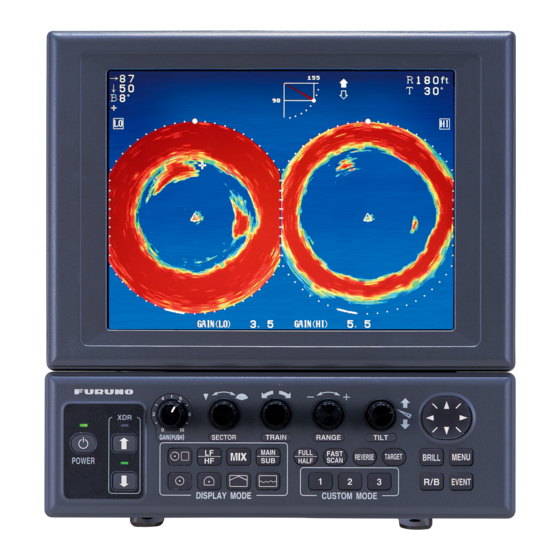
OPERATIONAL OVERVIEW Control Description Turns the power on/off. Raises the transducer Adjusts receiver sensitivity. Selects width of training sector. GAIN(PUSH) POWER Lowers the transducer. Turns mix display on/off. Low freq/High freq selection Horizontal Combination* DISPLAY MODE Horizontal Horizontal Expansion * Horizontal/History, Horizontal/Vertical scan, Horizontal/Vertical zoom, Horizontal/Video plotter Selects center bearing of training sector. -
Page 12: Remote Controller
1. OPERATIONAL OVERVIEW Remote Controller The Remote Controller CH-256 (option) provides armchair control over range, tilt, target lock and sounding range. Choose display range. Chooses sounding area: Full circle 360 (horizontal mode) Half circle 180 (vertical scan mode). Choose tilt angle. Enables/disables target lock. -
Page 13: Turning The Power On/Off
Turning the Power On/Off 1.3.1 Power on This sonar has a demonstration mode which provides simulated operation without the transducer. For further details see page 5-20. Press the POWER switch on the control unit till you hear a “click.” A beep sounds, the lamp above the switch lights and the startup display appears. -
Page 14: Raising, Lowering The Transducer
1. OPERATIONAL OVERVIEW Raising, Lowering the Transducer 1.4.1 Lowering the transducer Do not exceed 20 knots when operating the equipment and do not exceed 15 knots when lowering or raising the transducer. The transducer may become damaged. With the boat at the fishing ground, press the [↓] switch to lower the transducer. The lamp above the switch blinks while the transducer is being lowered and lights when it is completely lowered. -
Page 15: Adjusting Screen Brilliance, Panel Dimmer
Adjusting Screen Brilliance, Panel Dimmer Screen brilliance can be adjusted in 10 steps and panel dimmer (backlighting) in five. 1. Press the BRILL key to open the dialog box for screen brilliance and panel dimmer adjustment. Do the next step within four seconds, otherwise the dialog box will be erased. -
Page 16: Choosing A Display
1. OPERATIONAL OVERVIEW Choosing a Display 12 displays are provided; choose the one which best suits your current needs. For a description of each display, see Chapter 2. Single-frequency displays Display HORIZONTAL This mode provides 360 degree coverage. Useful for general search. (Chapter 2) VERTICAL SCAN Vertical section of underwater conditions appears on the entire screen. - Page 17 Dual-frequency displays Display DUAL-FREQ HORIZONTAL ° dual-freq. display of fish echoes, etc. (Chapter 2) DUAL-FREQ. VERTICAL SCAN Dual-freq. display of vertical section of fish echoes. Useful for judging depth and center position of fish school. (Chapter 3) DUAL-FREQ. HORIZ. EXPANSION Expansion of dual-freq.
- Page 18 1. OPERATIONAL OVERVIEW Combination displays Display Choose HORIZONTAL/HISTORY The horizontal picture appears in the main window; the history picture in the sub window. Useful for showing history of fish movement, distribution. (Chapter 2) Choose HORIZONTAL/VERTICAL SCAN The horizontal picture appears in the main window;...
-
Page 19: Choosing A Frequency
Choosing a Frequency You may choose low frequency or high frequency, with the LF/HF key. The display shows HI or LO at the top of the screen depending on your selection. Use the table below to determine which frequency to use. Item Long-range detection PREFERABLE... - Page 20 1. OPERATIONAL OVERVIEW Frequency selection and mode Single-frequency display or combination display (other than vertical scan combination): The LF/HF key chooses low frequency or high frequency alternately. Dual-frequency display (mix mode OFF): The LF/HF key switches the frequency of the high-and low-frequency displays alternately.
-
Page 21: Mix Display
Mix Display The mix display compares echo intensity between low and high frequencies, and displays echoes from tiny fish in discriminative colors. This is done by utilizing the fact that tiny fish return a stronger echo against a high frequency rather than a low frequency. The equipment accomplishes this as follows: •... - Page 22 1. OPERATIONAL OVERVIEW To use the mix display effectively, it is important that the gain for both the low and high frequencies is set properly. When searching for young fish such as whitebait, follow the procedure below. For detailed information about gain adjustment, see the next section. Gain adjustment 1.
-
Page 23: Adjusting The Gain
Adjusting the Gain The GAIN control adjusts the sensitivity of the receiver. Normally, the control is adjusted so that the bottom echo is displayed in reddish-brown mixed with red. Initially set the gain between “4” and “6” and then fine tune according to fishing ground, etc. Too Low Single-frequency or combination display When using both high and low frequency in the horizontal/vertical scan display, refer to the... - Page 24 1. OPERATIONAL OVERVIEW Dual-frequency display 1. Push the GAIN control. HIGH FREQ GAIN : LOW FREQ GAIN : 5.0 PUSH GAIN KNOB TO SPECIFY THE FREQ ROTATE GAIN KNOB TO CHANGE THE FREQ 2. Push the GAIN control to choose the frequency for which you want to adjust the gain. 3.
-
Page 25: Menu Overview
1.10 Menu Overview The menu, consisting of six menus, mostly contains items which once preset do not require frequent adjustment. Below is the procedure for basic menu operation. 1. Press the MENU key to open the menu. Note: Either PRESET (default setting) or SHORT-CUT appears between ES and SYS at the top of the screen depending on the setting of CUSTOM KEY on the SYSTEM SETTING 1 menu, and they set the function of the custom keys [1], [2], [3]. - Page 26 1. OPERATIONAL OVERVIEW This page intentionally left blank. 1-16...
-
Page 27: Horizontal Mode
HORIZONTAL MODE Operational Overview The figure below shows the typical horizontal mode operating sequence. 6(a). Set sector bearing range. Turn on the power. Adjust gain. GAIN(PUSH) POWER Lower the transducer. Set center bearing of train sector. Set range. SECTOR TRAIN RANGE MAIN FULL... -
Page 28: Typical Horizontal Mode Display
2. HORIZONTAL MODE Typical Horizontal Mode Display Press the (horizontal mode) key. Each press chooses the single frequency or dual- frequency horizontal mode display alternately. Single-freq. Display Switching between single-frequency horizontal and dual-frequency horizontal displays * Depth marker When depth data is input from external equipment, the depth marker shifts according to depth data. -
Page 29: Choosing A Range
Choosing a Range The RANGE control chooses the detection (display) range. Choose the range according to either the fish species being searched or the depth desired. 15 ranges are available and minimum and maximum ranges depend on the transducer used. BOTTOM Default horizontal mode range settings 80 100 120 160 200 250... -
Page 30: Choosing Sector Width
2. HORIZONTAL MODE Choosing Sector Width You may set the width of the scanned sector. The SECTOR control chooses the width of the scanned sector among the sixteen positions shown in the table below. Clockwise rotation of the control increases the sector width; counterclockwise rotation decreases it. -
Page 31: Choosing Train Center
Choosing Train Center The TRAIN control chooses the center direction of the detection range. The range of adjustment is 0° to 354° in increments of 6°. The selected bearing is shown with a filled circle, the train indicator, on the bearing scale. Choosing a Tilt Angle The tilt angle shown the direction to which the sound wave is emitted. -
Page 32: Tilt Angle For Surface Fish
2. HORIZONTAL MODE 2.6.1 Tilt angle for surface fish Sound emitted from the sonar transducer forms an oval-shaped beam with a width of approximately 10° (–3 dB, full scan, vertical beam width on 85 kHz) in the vertical direction (vertical beam width). The tilt angle is indicated by the angle between the center line is parallel with the sea surface and one half of the emitted sound goes upward, toward the sea surface. - Page 33 How to discriminate fish echoes from the bottom The figure at the bottom of the page illustrates how two fish schools “a” and “b” are displayed on the screen using three different tilt angles. Case 1 (Case 1, 2 and 3 are relative to the bottom pictured above.) Using the above three cases, fish schools will be displayed as below.
-
Page 34: Suitable Tilt Angle
2. HORIZONTAL MODE 2.6.3 Suitable tilt angle The figure below illustrates the relationship among tilt angle (0, 5, 10 and 15 degrees), depth and detection range. Refer to it to find out the suitable tilt angle for a given depth/detection range. Tilt angle and beam coverage (frequency 85 kHz, vertical beamwidth 10 (200) 20(40) -
Page 35: Choosing Training Speed
Choosing Training Speed The training speed chooses how fast the transducer scans the sounding sector. Two choices are available, normal speed (default setting) and high speed, and one may be selected with the FAST SCAN key. Each time the key is pressed “NORM” (normal speed) or “FAST”... -
Page 36: Finding Echo Position With The Cursor
2. HORIZONTAL MODE Finding Echo Position with the Cursor The cursor measures horizontal range, depth and bearing. Operate the Omnipad to place the cursor where desired. Cursor position data appears at the top left-hand corner on the screen. →: Horizontal range ↓: Depth B: Bearing 2-10... -
Page 37: 2.10 Event Marker
2.10 Event Marker The event marker functions to mark important locations on the horizontal mode display, and five event markers may be inscribed. Press the EVENT key to inscribe the event marker. Each time the key is pressed the “latest event marker” ( and all previously entered event markers are shown by the “previous event marker”... -
Page 38: Depth And Horizontal Range Markers
2. HORIZONTAL MODE Deleting all event markers from the horizontal display To delete all event markers inscribed on the horizontal mode display, do the following: 1. Operate the Omnipad to place the cursor outside the display area. 2. Press the EVENT key to show the following dialog box. Do the next step within four seconds, otherwise the dialog box will be erased. -
Page 39: 2.12 Adjusting The Picture
2.12 Adjusting the Picture 2.12.1 Suppressing bottom and surface reflections In shallow fishing grounds, excessive sea surface and bottom reflections often interfere with wanted fish echoes and they cannot be eliminated sufficiently with the TVG controls. In such cases, try to reduce the output power, without turning down the gain. The picture becomes clearer when output power is reduces rather than when the gain is decreased. -
Page 40: Suppressing Bottom Tail
2. HORIZONTAL MODE 2.12.2 Suppressing bottom tail As described earlier, fish schools near the bottom are sometimes difficult to detect because you have to discriminate fish echoes from the bottom reflections. To discriminate fish echoes near the bottom, choose the short Tx pulselength on the COM1 menu to decrease the tail of bottom reflections. - Page 41 To adjust TVG: 1. Press the MENU key to open the menu. 2. Press ▲ to choose MENU and then press ◄ or ► to choose HORZ. MENU TVG LEVEL TVG DISTANCE RES. COLOR CLUTTER TARGET KEY LOCK MODE AUTO TILT : SELECT 3.
-
Page 42: Erasing Weak Echoes
2. HORIZONTAL MODE 5. Press the MENU key to register your selection and close the menu. 6. To suppress reflections by the sea surface or plankton, choose TVG LEVEL and press ►. 7. Press ◄ or ► to adjust TVG LEVEL, considering sea conditions. A setting between 2.0 and 5.0 should provide satisfactory results. -
Page 43: Suppressing Interference From Marine Life
2.12.5 Suppressing interference from marine life If you are fishing in an area where there are a lot of fishing vessels, you may receive interference from other vessels’ sonar or echo sounder. Further, electrical interference onboard own ship may generate interference. To suppress this type of interference use the interference rejector. -
Page 44: Enlarging Fish Echoes (Horizontal Expansion Display)
2. HORIZONTAL MODE 2.12.6 Enlarging fish echoes (horizontal expansion display) Fish echoes may be enlarged 1.5 times by using the horizontal expansion display. Press the key to activate the horizontal expansion display (single frequency). Then, the horizontal display is expanded at the center of training direction, bow direction. Train center direction 318°... -
Page 45: 2.13 Target Lock
2.13 Target Lock Two types of target lock modes are available. Tracks stationary position (such as a reef) using position data from a Position: navigator. Available in the horizontal mode only. Tracks fish echo either manually or automatically. Available in the Echo: horizontal mode only. -
Page 46: Echo Mode
2. HORIZONTAL MODE 3. To turn off the target lock, press the TARGET key again. The message “LOCK END” momentarily appears, the target lock marker and the target lock indicator disappear and previously used sector, train and tilt settings are restored. Also, latitude and longitude indication returns to normal. - Page 47 Detection area Inner boundary When a target of red or reddish-brown color is detected in the zone, the target lock indicator blinks, the buzzer sounds and the detection area disappears. When a tracked target is lost, the operation shown below is repeated. Tilt changed to search [(A Detection area displayed once again and target lock indicator lights.
-
Page 48: 2.14 Horizontal Menu Overview
2. HORIZONTAL MODE 2.14 Horizontal Menu Overview This section presents an overview of the items on the HORZ menu. 1. Press the MENU key to open the menu. 2. Press ▲ to choose MENU and then press ◄ or ► to choose the HORZ menu. MENU TVG LEVEL TVG DISTANCE... - Page 49 2. HORIZONTAL MODE TARGET KEY: Chooses target lock function between position and echo. Default setting is ECHO. For further details see paragraph 2.13. LOCK MODE: Chooses how to track fish echo in ”echo” target lock; automatically or manually. Default setting is AUTO. For further details see paragraph 2.13. AUTO TILT: Turns automatic tilt on or off, and the default setting is OFF.
-
Page 50: 2.15 Interpreting The Horizontal Display
2. HORIZONTAL MODE 2.15 Interpreting the Horizontal Display This section provides information necessary for interpreting the horizontal display. 2.15.1 How the horizontal mode picture is painted The wide sounding beam is emitted from the soundome at a certain tilt angle (see hatched area in the figure below). -
Page 51: Sample Displays
2.15.2 Sample displays This section provides various examples of horizontal mode displays. The appearance of actual fish echoes will vary according to factors such as transmission frequency, gain and TVG settings, and bottom composition and contour. Bottom echoes When the tilt angle is changed, the bottom echo illustrated below will appear on the display. When the tilt is decrease (toward 0°), the bottom trace becomes winder and weaker. -
Page 52: Fish Schools
2. HORIZONTAL MODE Fish schools A fish school appears as a mass of echoes on the screen. The color of the mass shows the density of fish schools on the sonar beam. To find distribution and center point of a fish school, try several different tilt angles. - Page 53 Sea surface reflections To reduce sea surface reflections, set the tilt angle to 5° or higher, so the upper edge of the sonar beam does not hit the sea surface, or adjust TVG. When a decreased tilt angle is used, sea surface reflections cover a large area as illustrated below. °...
- Page 54 2. HORIZONTAL MODE Sidelobe echo (false echo) An ultrasonic wave is emitted only in the direction set by the TILT control, however there are some emissions outside the main beam. These are called sidelobes. The energy of the sidelobe is fairly weak but when the water is comparatively shallow and the bottom is rocky and hard, strong signals are detected by the sidelobe.
-
Page 55: Combination Display Examples
2.15.3 Combination display examples How to choose a combination display 1. Press the key to show the combination display selection window. HORZ/HISTORY HORZ/VERT HORZ/VERT ZOOM HORZ/PLOTTER 2. Use ▲ or ▼ to choose the combination display desired. You may also use the to choose a display. - Page 56 2. HORIZONTAL MODE Horizontal/history display The horizontal display appears in the main window; the history display in the sub window. The length of the picture displayed in the history display is equal to about four full circle pictures. Thus the history display enables you to observe the history of fish movement and distribution.
- Page 57 Horizontal/video plotter display The horizontal display appears in the main window; the video plotter display, which traces ship’s track on the display, in the sub window. Compared to the horizontal display the video plotter’s range is much longer. For example, an event marker entered on the horizontal display disappears from that display when it goes out of the current range.
- Page 58 2. HORIZONTAL MODE This page intentionally left blank. 2-32...
-
Page 59: Vertical Scan Mode
VERTICAL SCAN MODE Operational Overview The figure below shows the typical vertical scan mode operating sequence. 7(a). Set scanning sector. Turn on the power. Adjust gain. GAIN(PUSH) POWER Lower the transducer. Set train bearing. Set range. SECTOR TRAIN RANGE TILT MAIN FULL FAST... -
Page 60: Typical Vertical Scan Mode Display
3. VERTICAL SCAN MODE Typical Vertical Scan Mode Display Press the key to show the vertical scan display. You can switch between the single-frequency vertical scan display and the dual-frequency vertical scan display alternately with the key as shown below. Single-freq. -
Page 61: Choosing A Range
Choosing a Range The RANGE control chooses the detection (display) range, in 15 settings. Choose the range according to either the fish species being searched or the depth desired. Each time the control is operated the newly chosen range briefly appears in large characters at the screen top. -
Page 62: Choosing Train Center
3. VERTICAL SCAN MODE Choosing Train Center The TRAIN control determines the bearing of the vertical scan beam, from 0° to 180°. Bearing of beam position can be found with the train indicator. 0° (360°) 6° 12° 18° 180° Train Indicator Train of Vertical Fan Beam Train indicator TRAIN... -
Page 63: Choosing Display Sector
Choosing Display Sector Sector means the width of the transducer training, from 6° to 180°. The SECTOR control chooses the training area among the sixteen positions shown in the table below. Clockwise rotation of the control increases the sector width; counterclockwise rotation decreases it. -
Page 64: Choosing Sector Center
3. VERTICAL SCAN MODE Choosing Sector Center The center direction of the sounding beam in the vertical direction can be changed with the TILT control. The setting range is 0° to 180° in increments of 6°. Choose the setting which places the sector center in the middle of the detection range. -
Page 65: Choosing Training Speed
Choosing Training Speed The training speed chooses how fast the transducer scans the display sector. Two choices are available, 3° (normal speed, default setting) and 6° (high speed), and one may be selected with the FAST SCAN key. Each time the key is pressed the display momentarily shows “NORM”... -
Page 66: 3.10 Event Marker
3. VERTICAL SCAN MODE 3.10 Event Marker The event marker functions to mark important locations on the vertical scan display, and five event markers may be inscribed. Each time the EVENT key is pressed the “latest event marker” ( ⊕ ) is inscribed at the cursor location and all previously entered event markers are shown by the “previous event marker”... -
Page 67: Deleting All Event Markers From The Vertical Scan Display
3.10.1 Deleting all event markers from the vertical scan display All event markers inscribed on the vertical scan display may be deleted as follows: 1. Operate the Omnipad to place the cursor outside the display area. 2. Press the EVENT key to show the following dialog box. Do the next step within four seconds, otherwise the dialog box will be erased. -
Page 68: 3.12 Adjusting The Picture
3. VERTICAL SCAN MODE 3.12 Adjusting the Picture 3.12.1 Displaying weak echoes clearly Echoes from targets (such as the bottom or a fish) return to the transducer in order of the distance to them, and when their intensities are compared at the transducer face, those from nearer targets are generally stronger when their reflecting properties are nearly equal. -
Page 69: Suppressing Noise And Interference
4. Press ◄ or ► to adjust TVG distance, considering sea conditions. The larger the figure the greater the distance at which the TVG works. TVG Distance Setting Meters Feet Passi/braza Hiro 5. Press ▲ or ▼ to close the dialog box and return to the VERT menu. 6. -
Page 70: 3.13 Vertical Menu Overview
3. VERTICAL SCAN MODE 3.13 Vertical Menu Overview This section presents an overview of the items on the VERT menu. 1. Press the MENU key to open the menu. 2. Press ▲ to choose MENU and then press ◄ or ► to choose the VERT menu. MENU TVG LEVEL TVG DISTANCE... -
Page 71: Interpreting The Vertical Scan Display
HORZ SCAN RATE: Sets the scan rate (1, 2, 3, 4) for the horizontal display in the horizontal/vertical scan combination display. For example, if the scan for the horizontal display is “4” and the scan rate for the vertical scan display is “2”, then for every four scans at the horizontal display two scans are produced at the vertical scan display. -
Page 72: Sample Displays
3. VERTICAL SCAN MODE 3.14.2 Sample displays Port-starboard picture (bottom) You can see fish echoes at the center-right of the screen. The bottom is displayed wider as the distance from the ship’s position increases. Therefore, it may be difficult to discriminate bottom fish. - Page 73 3. VERTICAL SCAN MODE Display of net hauling This is an example of net hauling display. The location of the net is indicated clearly. Own ship FORE Net hauling and sonar picture False echo In shallow water (depth less than 100 m) detection, unwanted echoes shown in the figure may appear.
-
Page 74: Horizontal/Vertical Scan Port-Starboard, Horizontal/Vertical Scan Upward-Downward Display
3. VERTICAL SCAN MODE 3.14.3 Horizontal/vertical scan port-starboard, Horizontal/vertical scan upward-downward display Vertical scan Cursor data bearing cursor B156° Own ship marker Train position Cursor Horizontal Display (main window) Horizontal/vertical scan display (port-starboard direction) 3-16 Frequency Tilt angle Tilt angle indicator Range 40 m 40°... - Page 75 B 288 Horizontal Display (main window) Vertical Scan Display (sub window) Horizontal/vertical scan display (upward-downward direction) Press the key to choose and display the horizontal/vertical scan display. The horizontal display appears in the main window; the vertical scan display in the sub window. The displays are independent of each other so you can adjust them as desired.
- Page 76 3. VERTICAL SCAN MODE SECTOR control For the vertical scan display: When the display sector is 6° (minimum) the tilt angle of the horizontal and vertical scan modes are interlocked and each transmission on the horizontal display is reflected on the vertical scan display. The message TILT ANGLE MONITOR WINDOW momentarily appears on the screen and the vertical bearing cursor disappears.
-
Page 77: Echo Sounder Mode
ECHO SOUNDER MODE Operational Overview The figure below shows the typical echo sounder mode operating sequence. Turn on the power. Adjust gain. GAIN(PUSH) POWER Lower the transducer. Set sector. Set train bearing. Set range. SECTOR TRAIN RANGE MAIN FULL FAST REVERSE HALF SCAN... -
Page 78: Typical Echo Sounder Display
4. ECHO SOUNDER MODE Typical Echo Sounder Display Press the key to display the echo sounder picture. You can switch between the single-frequency echo sounder display and the dual-frequency echo sounder display alternately with the key as shown below. Depth/Temp. Display Single-freq. -
Page 79: Choosing A Range
Choosing a Range The RANGE control chooses the detection (display) range, in 15 settings. Choose the range according to either the fish species being searched or the depth desired. Each time the control is operated the newly chosen range briefly appears in large characters at the screen top. -
Page 80: Train Direction
4. ECHO SOUNDER MODE Train Direction The sounding beam may be directed toward fore, aft, port or starboard. Operate the TRAIN control to choose sounding beam direction. Each setting on the control is an increment of 6°. The train indicator at the top of the screen shows training direction: 0°, fore direction; 90°, starboard direction;... -
Page 81: Measuring Range By Cursor
4. ECHO SOUNDER MODE Measuring Range by Cursor Use the cursor to display the range from own ship to the cursor location. Use the Omnipad to place the cursor where desired. The range to the cursor appears at the upper left-hand corner of the screen. -
Page 82: Inscribing The Event Marker
4. ECHO SOUNDER MODE 4.8.1 Inscribing the event marker 1. Operate the Omnipad to place the cursor on the location desired for an event marker. 2. Press the EVENT key to inscribe the event marker. "Previous event marker" Depth, Water Temp. Display "Latest event marker"... -
Page 83: Range Marker
Range Marker The range marker functions to measure the range to a target echo (fish school, bottom, etc.) 1. Operate the Omnipad to place the cursor on the location desired. 2. Press the R/B key to display the range marker. The range marker appears along with range indication. - Page 84 4. ECHO SOUNDER MODE MENU COM1 TVG LEVEL TVG DISTANCE RES. COLOR CLUTTER A-SCOPE : SELECT 3. Press ▲ or ▼ to choose TVG DISTANCE and press ►. The following dialog box appears. TVG DISTANCE 200m 4. Press ◄ or ►or to adjust TVG distance. TVG Distance Setting Meters...
-
Page 85: Finding Echo Strength (A-Scope Display)
4.10.2 Finding echo strength (A-scope display) The A-scope display shows echoes at each transmission with amplitudes and tone proportional to their intensities on the right 1/4 of the screen. It is useful for estimating the kind of fish school and bottom composition. 1. -
Page 86: 4.11 Echo Sounder Menu Overview
4. ECHO SOUNDER MODE 4.11 Echo Sounder Menu Overview This section presents an overview of the items on the ES menu. 1. Press the MENU key to open the menu. 2. Press ▲ to choose MENU and then press ◄ or ► or to choose the ES menu. MENU TVG LEVEL TVG DISTANCE... -
Page 87: Menu Operation
MENU OPERATION This chapter provides menu operating information on menus not previously discussed: COM1, COM2, PRESET (or SHORT-CUT, depending on the setting of CUSTOM KEY on the SYSTEM SETTING 1 menu) and SYS (System) menu. COM1 Menu 1. Press the MENU key to open the menu. 2. -
Page 88: Com1 Menu Description
5. MENU OPERATION 5.1.1 COM1 menu description TX POWER: Chooses transmitter output power to maximum or minimum. The default setting is "maximum." For further details see paragraph 2.12.1. PULSELENGTH: Chooses pulselength to short or long (default setting). For details see paragraph 2.12.2. -
Page 89: Com2 Menu
COM2 Menu 5.2.1 Displaying the COM2 menu 1. Press the MENU key to open the menu. 2. Press ▲ to choose MENU, and then press ◄ or ► to choose COM2. MENU DELETING TRACK MIX MODE WHITE MARKER SIG LEVEL COLOR BKGD COLOR : SELECT... -
Page 90: Short-Cut Menu, Preset Menu
5. MENU OPERATION Short-cut Menu, Preset Menu These menus program the CUSTOM MODE keys [1], [2] and [3], and one of the menus appears according to the setting of CUSTOM KEY on the SYSTEM SETTING 1 menu. Short-cut key: One-touch activation of corresponding dialog box. This is the default setting. Preset key: One-touch setup of mode, sector, train, range, tilt and speed controls. -
Page 91: Preset Key
5. Press ► to open the SYSTEM SETTING menu. MENU POSITION TRACK CURRENT DATA HEADING INDICATION : TRUE NORTH MARK CSE DATA NAV DATA NAV2 BAUDRATE TVG CORRECTION UNIT TEMP TARGET L/L CUSTOM KEY ETA MARK : CHANGE : SELECT System setting 1 menu 6. - Page 92 5. MENU OPERATION 4. Set the MODE, HI/LO, SECTOR, TRAIN, RANGE and TILT controls according to target fish or fishing area. 5. Press the CUSTOM MODE keys [1], [2] or [3] to program. You are asked if you want to save the settings to the custom key pressed.
-
Page 93: Short-Cut Key
5.3.3 Short-cut key The default settings are key [1], interference rejector; key [2], signal level, and key [3], background color. The operator may change their functions as desired. Note: In the combination modes the short-cut key operation is only possible from the main window. - Page 94 5. MENU OPERATION VERTICAL SEARCH FUNCTION When you find a target of interest on the horizontal display, simply press the function key programmed for VER. SEARCH to get a cross-sectional view of the vertical plane. This mode is useful for evaluating fish school concentration and location of the targeted fish school or for assistance in navigation.
-
Page 95: System Menu
SYSTEM Menu This menu provides items which may be set according to operator’s preference. A demonstration mode is provided to acquaint you with the many functions of this equipment, and it may be used without connection of the transducer. 5.4.1 How to open the SYSTEM menu 1. -
Page 96: System Setting Menus
5. MENU OPERATION 5.4.2 System setting menus SYSTEM SETTING 1 menu 1. Display the SYSTEM menu and press ▲ or ▼ to choose SYSTEM SETTING. 2. Press ►. 3. Press ▲ to MENU. 4. Press ◄ to choose “1.” ** SYSTEM SETTING 1 ** MENU POSITION TRACK... - Page 97 5. MENU OPERATION HEADING INDICATION: Chooses heading indication format, true (default setting) or azimuth, for the echo sounder and vertical scan modes. The default setting is TRUE. Requires heading data. NORTH MARK: Turns the north marker on or off (default setting). Requires heading data. CSE DATA: Chooses heading data source, navigator or gyrocompass, to draw ship’s track.
- Page 98 5. MENU OPERATION SYSTEM SETTING 2 menu description MENU GAIN SETTING PROTECT : HORZ/HISTORY HORZ/VERT HORZ/VERT ZOOM HORZ/PLOTTER EMPHASIS MODE STABILIZER AUTO RETRACTION SPEED ALARM/MESSAGE: SWEEP INDICATOR DEFAULT SETTING MAXIMUM ALLOWABLE SPEED IS 15 KNOTS WHILE SOUNDOME IS BEING RETRACTED. IF VESSEL HAS RAPID ACCELERATION CAPABILITIES, AUTO RETRACTION SETTINGS OF 10-12 KNOTS ARE MANDATORY TO AVOID CATASTROPHIC DAMAGE TO SOUNDOME ASSY.
- Page 99 AUTO RETRACTION: Turn on to automatically retract the transducer when ship’s speed exceeds the speed set here. The ship’s speed range for automatic retraction is from 5 to 15 knots. The default setting is OFF (no automatic retraction). The transducer may be retracted at a speed other than the intended one when ship’s speed data is erroneous.
-
Page 100: Sonar (Horizontal) Mode Range Settings
5. MENU OPERATION 5.4.3 Sonar (horizontal) mode range settings The user may preset horizontal mode ranges as desired. 1. Choose RANGE-SONAR MODE at the SYS menu and then press ►. ** RANGE-SONAR MODE ** DEFAULT SETTING : : CHANGE : SELECT Range-sonar mode dialog box 2. -
Page 101: Vertical Scan Mode Range Settings
5.4.4 Vertical scan mode range settings As with the horizontal mode, the user may preset the vertical scan mode’s ranges. 1. Choose RANGE-VERTICAL MODE at the SYS menu and then press ►. ** RANGE-VERT MODE ** DEFAULT SETTING : : CHANGE : SELECT Range-vert mode dialog box 2. -
Page 102: Echo Sounder Mode Range Settings
5. MENU OPERATION 5.4.5 Echo sounder mode range settings As with the horizontal and vertical scan modes, the user may preset the echo sounder mode’s ranges. 1. Choose RANGE-E/S MODE at the SYS menu and then press ►. ** RANGE-E/S MODE ** DEFAULT SETTING : : CHANGE : SELECT... -
Page 103: Track Range Settings
5.4.6 Track range settings You may choose the video plotter display scale range as follows. 1. Choose RANGE-TRACK at the SYS menu and then press ►. ** RANGE-TRACK MODE ** DEFAULT SETTING : : CHANGE : SELECT Range-track mode dialog box 2. -
Page 104: Color Palette
5. MENU OPERATION 5.4.7 Color palette The color palette lets the user change the color of echoes, background, text and menu as desired. Cursor ECHO Arrow BKGD TEXT BKGD1 COLOR : ECHO 1 DEFAULT SETTING : : SELECT 1. Press ◄ or ► to place the cursor and arrow on the item to change. Pressing ► shifts the arrow and cursor from left to right and top to bottom. -
Page 105: Language
5.4.8 Language Menu language can chosen from among the languages shown in the Language dialog box and the default language is English. LANGUAGE: : CHANGE 5.4.9 System backup User settings can be backed up with the menu item SYSTEM BACKUP. ARE YOU SURE? NOTE: OVERWRITES PREVIOUS BACKUP DATA. -
Page 106: Transducer Frequency Adjustment
5. MENU OPERATION 5.4.11 Transducer frequency adjustment If the CH-300 is receiving interference from a video sounder or other sonar on board your ship, adjust the frequency of the CH-300’s transducer to reduce the interference. FREQ SHIFT (L) FREQ SHIFT (H) -
Page 107: Restoring All Default Settings
5.4.13 Restoring all default settings The item DEFAULT lets you restore all default menu settings. Choose YES and press the MENU key to restore all default settings. Note that SOUNDOME SER. NO (SYSTEM SETTING2 menu) and the contents stored by using the SYSTEM BACKUP feature (paragraph 5.4.9) are not disturbed. - Page 108 5. MENU OPERATION This page intentionally left blank. 5-22...
-
Page 109: Maintenance, Troubleshooting
MAINTENANCE, TROUBLESHOOTING This chapter provides information necessary for keeping the equipment in good working order. Preventive Maintenance Check the following points monthly. • Check all cables. If damaged, replace. • Check connectors at rear of each unit. Clean if necessary. •... -
Page 110: Hull Unit Maintenance
6. MAINTENANCE, TROUBLESHOOTING Hull Unit Maintenance 6.3.1 Lubrication Grease the raise/lower screw shaft once a year. Also, grease the raise/lower main shaft (upper part of the grease cotton retainer) twice a year. These parts can be accessed by removing the raise/lower drive assembly cover. 6.3.2 Manually raising, lowering transducer Turn off the power at the ship's mains... -
Page 111: Transducer Maintenance
Transducer Maintenance When the ship is dry-docked remove marine growth from the transducer with fine sandpaper or a piece of wood. Coat the transducer face with anti-fouling paint (Chugoku MarineStar 20 Red or the equivalent) Do not paint the transducer face. Loss of sensitivity will result. -
Page 112: Troubleshooting
• Debris may be on sea surface. Reject unwanted noise with the interference rejector on the COM1 menu. • Problem in tilt mechanism or control line. Contact a FURUNO agent Picture does not change when tilt or dealer for advice. -
Page 113: 6.7 Error Messages
6.7 Error Messages The table below shows the error messages which may appear on the display. All error messages are accompanied by an audio alarm, which you may silence with the R/B key. Message Hull Unit HULL UNIT POWER OFF (CHECK BREAKER AND FUSE.) PRESS R/B KEY TO SILENCE ALARM. -
Page 114: Diagnostics
• The ROM, RAM, VRAM, NMEA1, NMEA2 and PANEL CPU are checked for proper operation and the results displayed as OK or NG (No Good). For NG contact a FURUNO agent or dealer for advice. The NMEA1/NMEA2 test checks the NMEA (monitor unit) / NMEA (transceiver unit) ports. - Page 115 • TRAIN shows a figure between 355-359 if normal. NG appears in case of train error. • TEST COUNT shows the number of times the test has been consecutively executed. • At the bottom of the screen there are two major groups of zeroes (0), and they represent the keys and controls on the control panel and remote controller.
-
Page 116: Test Pattern
6. MAINTENANCE, TROUBLESHOOTING Test Pattern A test pattern can be displayed to check for proper display of colors. 1. Press the MENU key to open the menu. 2. Press ▲ to choose MENU, and then press ► to choose SYS. 3. -
Page 117: Menu Tree
MENU TREE [MENU] key COM1 menu TX POWER ( MAX , MIN) PULSELENGTH ( LONG , SHORT) TX RATE (EXTERNAL, 1-10; 10 ) INT REJECT ( OFF , ON) AGC ( OFF , ON) AUDIO LEVEL ( 0 -10) COM2 menu DELETING TRACK ( NO , YES) MIX MODE ( STANDARD , EMPHASIS) WHITE MARKER (8-color: OFF , 1-7;... - Page 118 MENU TREE (CONTINUED FROM PREVIOUS PAGE) SYSTEM menu SYSTEM SETTING (See below.) RANGE-SONAR MODE (all default ranges) m: 20, 40, 60, 80, 100, 120, 160, 200, 250, 300, 400, 500, 600, 800, 1200 ft: 50, 100, 200, 300, 400, 500, 600, 700, 800, 1000, 1200, 1500, 2000, 3000, 4000 fa: 10, 20, 40, 60, 80, 100, 120, 140, 160, 200, 250, 300, 400, 500, 700 P/B, Hiro: 10, 20, 40, 60, 80, 100, 120, 160, 200, 250, 300, 400, 500, 600, 800 RANGE-VER MODE (all default ranges)
- Page 119 Vertical scan mode, echo sounder mode Meter Min. range Max. range MONITOR/CONTROL UNIT 2.1 Display 2.2 Brilliance 2.3 Display Colors CH-300 10.4-inch color TFT LCD (or external monitor) Dual frequency, 60/153 kHz or 85/215 kHz 1.0 kW Feet Fathom Vert Horz...
- Page 120 Scanning angle: 6° to 360°, 24° step Scanning center: 6° steps, 360° setting available Scanning step angle: Normal: 6°, High speed: 12° Elevation angle: +5° to 90°, 1° step Auto tilt setting: ±2° to ±10° SP - 2 CH-300 1200 1200 E125S01A...
- Page 121 MU-100C: IPX5 2 Hz-5Hz to 13.2 Hz: Amplitude: ±1 mm ±10% 13.2 Hz to 100 Hz: Max. acceleration 7m/s Panel: N3.0, Chassis: 2.5GY5/1.5 2.5GY5/1.5 Panel: N3.0 Newtone No.5, Chassis: 2.5GY5/1.5 SP - 3 CH-300 Vertical 14°/20° 10°/14° 5°/8° 4°/6° , fixed...
- Page 122 This page is intentionally left blank.
-
Page 123: Index
INDEX AGC ...5-2 A-scope display ...4-9 Automatic tilt ...2-23 Background color...5-2 Backup data loading ...5-19 saving ...5-19 BRILL control ...1-5 Clutter echosounder mode...4-10 horizontal mode ...2-22 vertical scan mode ...3-12 Color palette ...5-18 Colors background...5-3 display...5-3 COM1 menu ...5-1 COM2 menu ...5-3 Control description...1-1 Course data ...5-11 Current (tide) data ...5-10... - Page 124 INDEX MAIN/SUB key... 2-31, 3-17 Maintenance hull unit ...6-2 preventive ...6-1 replacement of fuse...6-3 transducer...6-3 MENU key ...1-15 Menu tree ...1 Mix display... 1-11 MIX key... 1-11 Navigation data... 5-11 North marker... 5-11 Position display format ...5-10 POWER switch ...1-3 PRESET menu ...5-5 Pulselength...2-14 R/B key...
Need help?
Do you have a question about the CH-300 and is the answer not in the manual?
Questions and answers