
Related Manuals for Scania Interlock 7 00 Series


Summary of Contents for Scania Interlock 7 00 Series
- Page 1 ® SCANIA Interlock 7x00 More languages at Scania Vehicle Accessories Online: accessories.scania.com Installation instructions sv · en · fr · de · es...
- Page 2 Installationsanvisning ..............3 Installation instructions..............18 Notice d'installation ..............33 Installationsanweisung ..............48 Instrucciones de instalación ............63 ® SCANIA Interlock 7x00...
-
Page 3: Table Of Contents
Innehållsförteckning Innehållsförteckning SCANIA Interlock ® 7x00 Säkerhetsrelaterade informationer ........4.10 Monteringsintyg ................. 4.11 Inställning och kalibrering av alkolåset ........Konventioner i det här dokumentet ........4.12 Demontera Interlock ..............4.12.1 Bortkoppling av fordonets batteri ..........Varningarnas betydelse.............. 4.12.2 Lossa anslutningsledningar ............ -
Page 4: Säkerhetsrelaterade Informationer
OBSERVERA Potentiell risksituation. Att inte undvika denna risk kan leda till personskador. Kan också användas som varning för icke fackmässig användning. NOTERING Potentiell risksituation. Om denna inte undviks kan skador på produkten eller miljön orsakas. Installationsanvisning ® SCANIA Interlock 7x00... -
Page 5: Beskrivning
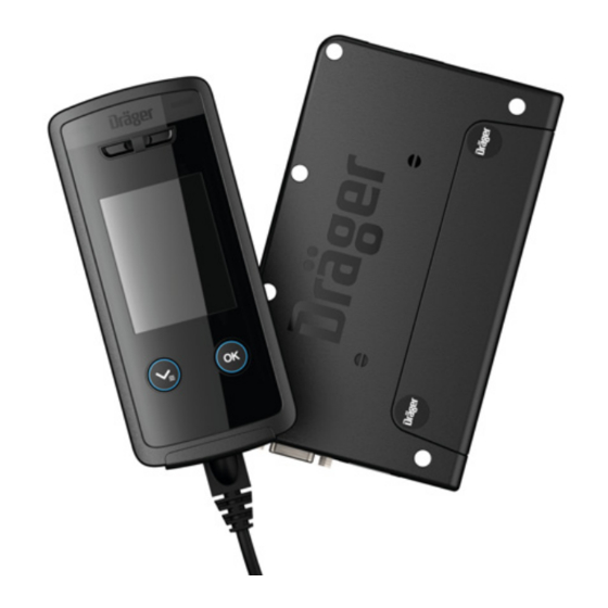
Beskrivning Beskrivning Produktöversikt Interlock 7x00 12 11 Installationsanvisning ® SCANIA Interlock 7x00... -
Page 6: Beskrivning Av Anslutningsledningarna På Kontrollboxen
Ingång, High aktiv för startdetektering Beskrivning av anslutningsledningarna på (D+/generator) kontrollboxen Plinttilldelning Färg Beskrivning grå Potentialfri kopplingsutgång för startfri- givning (t.ex. plint 50) brun orange Relä för anslutning till exempel av strål- kastarna (tillval) lila Installationsanvisning ® SCANIA Interlock 7x00... -
Page 7: Installation
Ledningar, anslutning av Kontrollera om det finns fordonsspecifika monteringsanvisningar och följ dessa. En lista över befintliga monteringsanvisningar finns hos Dräger. Interlock är ett registrerat varumärke som tillhör Dräger. Installationsanvisning ® SCANIA Interlock 7x00... -
Page 8: Fastställa Fordonets Plint 15 För Interlock-Installation
● Lossa den negativa polklämman från fordonets batteri innan du fortsätter med arbetet. Att frånkoppla fordonsbatteriet raderar eventuella batteriberoende instrumentinställningar (t.ex. stöldkoden eller radions kanalinställningar). I vissa fordon kan frånkoppling av fordonsbatteriet leda till att krockkuddens indikatorlampa tänds, vilket endast kan återställas av fordonstillverkaren. Installationsanvisning ® SCANIA Interlock 7x00... -
Page 9: Exempel På Kopplingsschema (I Det Här Fallet Med Nyckelbrytare Och Startrelä)
Installation 4.4.3 Exempel på kopplingsschema (i det här fallet med nyckelbrytare och startrelä) Installationsanvisning ® SCANIA Interlock 7x00... -
Page 10: Jord
Om instrumentet inte kopplar om till fristarttid när motorn stängs av ur är D+- 2. Klipp vid behov av tändningens anslutningsledning (blå) på styrenheten. ledningen inte korrekt ansluten. 3. Sätt Dräger krympslang på tändningens anslutningsledning. Installationsanvisning ® SCANIA Interlock 7x00... -
Page 11: Ansluta Hastighetsmätarsignal
PIN 16 i stället för generatorutgången D+ ifall den ger en frekvens mellan 1 och 500 Hz proportionellt mot fordonets hastighet. ● Välj ett gränsvärde som gör att fordonets rörelser detekteras från och med en hastighet på ca. 3 km/h. Omräkningsfaktorn kan erhållas från fordonstillverkaren. Installationsanvisning ® SCANIA Interlock 7x00... -
Page 12: Elschema Med D+-Ledning Eller Hastighetsmätarsignal
Installation 4.4.10 Elschema med D+-ledning eller hastighetsmätarsignal Installationsanvisning ® SCANIA Interlock 7x00... -
Page 13: Ansluta Signalhorn Och Strålkastare
1. Välj ett lämpligt monteringsställe, som är väl synligt för föraren, men som inte hindrar hans sikt (till exempel på rattstångens hölje eller ovanför instrumenttavlan). 2. Montera indikeringslampan och anslut den till instrumentet (anslutningar 12 LED+ och 13 LED- (se "Beskrivning av anslutningsledningarna på kontrollboxen", sida 6)). Installationsanvisning ® SCANIA Interlock 7x00... -
Page 14: Dörrkontakt
Kontrollera att funktionen hos instrumentet motsvarar bruksanvisningen. 1. Interlock vaknar när tändningen aktiveras (anslutning 15) eller via en digital 2. Dra och fäst kontrollboxens kablar på befintliga kabelstammar och så ingång (t.ex. att fordonets kupébelysning tänds/fordonet låses upp). osynligt som möjligt. Installationsanvisning ® SCANIA Interlock 7x00... -
Page 15: Monteringsintyg
Denna produkt får inte kastas som hushållsavfall. Den betecknas därför ● Om nödvändigt kalibrera instrumentet. med symbolen nedan. Produkten kan kostnadsfritt returneras till Dräger. Information om detta fås från de nationella återförsäljarna samt från Dräger. Installationsanvisning ® SCANIA Interlock 7x00... -
Page 16: Tekniska Data
<1 mA Hållare för handenhet 83 22 497 Brytrelä för startreläets ledning Hållare II för handenhet II 83 22 610 kontinuerlig <16 A Spiralkabel, längd 1,5 m 83 15 909 Topp <40 A Installationsanvisning ® SCANIA Interlock 7x00... - Page 17 Beställningslista Beteckning och beskrivning Ordernr. Spiralkabel, längd 5,5 m 83 20 248 Installationsanvisning ® SCANIA Interlock 7x00...
- Page 18 Contents Contents SCANIA Interlock ® 7x00 Safety-related information............4.10 Installation certificate..............4.11 Instrument setting and calibration ..........4.12 Conventions in this document..........Removing the Interlock............... 4.12.1 Disconnecting the vehicle battery..........Meaning of the warning notices ..........4.12.2 Detaching the connecting leads ..........
-
Page 19: Safety-Related Information
If not avoided, it could result in physical injury. It may also be used to alert against unsafe practices. NOTICE Indicates a potentially hazardous situa- tion. If not avoided, it could result in damage to the product or environment. Installation instructions ® SCANIA Interlock 7x00... -
Page 20: Description
Description Description Product overview Interlock 7x00 12 11 Installation instructions ® SCANIA Interlock 7x00... -
Page 21: Description Of The Connection Leads On The Control Unit
Input, active high for start recognition white (D+/alternator) control unit Terminal assign- Colour Description ment grey Floating switching output for clearance to start (e.g., terminal 50) brown orange Relay for connection, such as for head- lights (optional) purple Installation instructions ® SCANIA Interlock 7x00... -
Page 22: Installation
Check for any installation instructions specific to the vehicle, and if these exist, continue by following those instructions. A list of available installation instructions can be obtained from Dräger. Interlock is a registered trademark of Dräger. Installation instructions ® SCANIA Interlock 7x00... -
Page 23: Identifying Terminal 15 In The Vehicle For Interlock Installation
(e.g. the theft code for the radio or the preset stations). On some vehicles, disconnecting the vehicle battery may turn the airbag light on, which can then only be turned off by the vehicle manufacturer. Installation instructions ® SCANIA Interlock 7x00... -
Page 24: Example Of Circuit Diagram (Here With Key Switch And Starter Relay)
Installation 4.4.3 Example of circuit diagram (here with key switch and starter relay) Installation instructions ® SCANIA Interlock 7x00... -
Page 25: Connecting The Earth Lead
D+ lead is either not connected or has not been properly 2. Trim, as necessary, ignition lead on the control unit (blue). connected. 3. Place Dräger thermo-shrinkable tubing on the ignition lead. Installation instructions ® SCANIA Interlock 7x00... -
Page 26: Connecting The Speedometer Signal
Pin 16 can also be connected if this provides a frequency between 1 and 500 Hz proportional to the driven speed. ● Select the threshold of a vehicle movement from a speed of approx. 3 km/h. Request the conversion factor from the vehicle manufacturer. Installation instructions ® SCANIA Interlock 7x00... -
Page 27: Connection Diagram With D+ Lead Or Speedometer Signal
Installation 4.4.10 Connection diagram with D+ lead or speedometer signal Installation instructions ® SCANIA Interlock 7x00... -
Page 28: Connecting The Horn And Headlights
(for example on top of the cover of the steering column or above the instrument panel). 2. Mount indicator lights and connect to the device (connections 12 LED+ and 13 LED- (see "Description of the connection leads on the control unit", page 21)). Installation instructions ® SCANIA Interlock 7x00... -
Page 29: Connecting The Door Contact
Test the function of the device in line with the instructions for use. Cable ties 1. The Interlock wakes up when the ignition is switched on (Connection 15) or Steering column via a digital input (e.g. vehicle interior lighting switched on/vehicle unlocked). Installation instructions ® SCANIA Interlock 7x00... -
Page 30: Installation Certificate
This product must not be disposed of as household waste. This is indi- cated by the adjacent symbol. ● Calibrate the device, if necessary. You can return this product to Dräger free of charge. For information please contact the national marketing organizations or Dräger. Installation instructions ® SCANIA Interlock 7x00... -
Page 31: Technical Data
83 22 497 Switch relay for the lead for the starter relay Holster II for handset II 83 22 610 continuous <16 A Spiral cord, length 1.5 m 83 15 909 peak <40 A Installation instructions ® SCANIA Interlock 7x00... - Page 32 Order list Name and description Order no. Spiral cord, length 5.5 m 83 20 248 Installation instructions ® SCANIA Interlock 7x00...
- Page 33 Sommaire Sommaire SCANIA Interlock ® 7x00 Informations relatives à la sécurité........Contrôle du fonctionnement............4.10 Certificat de montage..............Conventions utilisées dans ce document ......4.11 Réglage et calibrage de l'appareil..........4.12 Démontage de l’Interlock ............Signification des avertissements ..........4.12.1 Déconnexion de la batterie du véhicule........
-
Page 34: Informations Relatives À La Sécurité
Peut éga- lement être utilisé pour avertir d'une utili- sation incorrecte. REMARQUE Signale une situation potentiellement dangereuse qui, si elle n'est pas évitée, peut avoir des conséquences néfastes pour le produit ou l'environnement. Notice d'installation ® SCANIA Interlock 7x00... -
Page 35: Description
Description Description Aperçu du produit Interlock 7x00 12 11 Notice d'installation ® SCANIA Interlock 7x00... -
Page 36: Description Des Câbles De Raccordement Sur La Centrale
Couleur Description bornes (D+ / alternateur) gris Sortie de commutation sans potentiel pour l’autorisation du démarrage (par marron exemple borne 50) orange Relais pour le raccordement des phares par exemple (en option) violet Notice d'installation ® SCANIA Interlock 7x00... -
Page 37: Installation
Fixation avec des colliers de câblage. 4.3.2 Combiné AVERTISSEMENT Ne pas installer le support du combiné devant les airbags. Interlock est une marque déposée de Dräger. Notice d'installation ® SCANIA Interlock 7x00... -
Page 38: Raccordement Des Lignes
équipés d’une centrale à bus CAN, il est possible d’utiliser un adaptateur pour bus CAN pour générer une borne 15. Notice d'installation ® SCANIA Interlock 7x00... -
Page 39: Exemple De Schéma Électrique (Ici Avec Interrupteur À Clé Et Relais De Démarrage)
Installation 4.4.3 Exemple de schéma électrique (ici avec interrupteur à clé et relais de démarrage) Notice d'installation ® SCANIA Interlock 7x00... -
Page 40: Raccordement Du Fil De Masse
1. Couper le fil d'allumage dans le faisceau du commutateur d'allumage de manière à disposer d'une longueur suffisante pour le raccordement au fil d'allumage (bleu) de l'unité de commande. 2. Au besoin, raccourcir le fil d'allumage (bleu) de l'unité de commande. Notice d'installation ® SCANIA Interlock 7x00... -
Page 41: Connexion Du Signal Du Tachymètre
à laquelle le véhicule roule. ● Sélectionner la valeur limite de façon que le système détecte que le véhicule se déplace à partir d’une vitesse d’environ 3 km/h. Demander le facteur de conversion auprès du constructeur du véhicule. Notice d'installation ® SCANIA Interlock 7x00... -
Page 42: Schéma Électrique Avec Fil D+ Ou Signal Du Tachymètre
Installation 4.4.10 Schéma électrique avec fil D+ ou signal du tachymètre Notice d'installation ® SCANIA Interlock 7x00... -
Page 43: Raccordement Du Klaxon Et Des Phares
2. Fixer l'éclairage de l'affichage et le raccorder à l'appareil (raccords 12 LED+ et 13 LED- (Voir "Description des câbles de raccordement sur la centrale", page 36)). Notice d'installation ® SCANIA Interlock 7x00... -
Page 44: Raccordement Du Contact De Portière
Contrôle du fonctionnement Exemple : REMARQUE Centrale Rebrancher la batterie du véhicule après l'installation. Contrôler le fonctionnement de l'appareil conformément à la notice d'utilisation. Collier de câblage Colonne de direction Notice d'installation ® SCANIA Interlock 7x00... -
Page 45: Certificat De Montage
6. Après le démontage de l'appareil, rebrancher la batterie du véhicule. 4.11 Réglage et calibrage de l'appareil Ces opérations doivent exclusivement être effectuées par un centre SAV Dräger-Interlock autorisé. Notice d'installation ® SCANIA Interlock 7x00... -
Page 46: Elimination
Embouts buccaux (lot de 5) emballés indivi- 83 26 550 duellement Centrale env. 148 mm x 90 mm x 32 mm Poids Embouts buccaux (lot de 50) emballés indivi- 83 27 627 duellement Combiné env. 240 g Notice d'installation ® SCANIA Interlock 7x00... - Page 47 37 01 239 rieurs (AUX/OUT) Support du combiné 83 22 497 Support II du combiné II 83 22 610 Câble spiralé, longueur 1,5 m 83 15 909 Câble spiralé, longueur 5,5 m 83 20 248 Notice d'installation ® SCANIA Interlock 7x00...
- Page 48 Inhaltsverzeichnis Inhaltsverzeichnis SCANIA Interlock ® 7x00 Sicherheitsbezogene Informationen ........4.10 Einbaubescheinigung ..............4.11 Geräteeinstellung und Kalibrierung ..........Konventionen in diesem Dokument ........4.12 Interlock ausbauen ..............4.12.1 Fahrzeugbatterie abklemmen............. Bedeutung der Warnhinweise............ 4.12.2 Anschlussleitungen trennen ............Beschreibung ................Entsorgung................Produktübersicht ................
-
Page 49: Sicherheitsbezogene Informationen
Wenn diese nicht vermieden wird, können Verletzungen eintreten. Kann auch als Warnung vor unsachge- mäßem Gebrauch verwendet werden. HINWEIS Hinweis auf eine potenzielle Gefahrensi- tuation. Wenn diese nicht vermieden wird, können Schädigungen am Produkt oder der Umwelt eintreten. Installationsanweisung ® SCANIA Interlock 7x00... -
Page 50: Beschreibung
Beschreibung Beschreibung Produktübersicht Interlock 7x00 12 11 Installationsanweisung ® SCANIA Interlock 7x00... -
Page 51: Beschreibung Der Anschlussleitungen An Der Steuereinheit
(konfigurierbar) der Steuereinheit Eingang, High aktiv für Starterkennung weiß (D+/Lichtmaschine) Klemmenbele- Farbe Beschreibung gung grau Potentialfreier Schaltausgang für Start- freigabe (z. B. Klemme 50) braun orange Relais für Anschluss zum Beispiel der Scheinwerfer (optional) violett Installationsanweisung ® SCANIA Interlock 7x00... -
Page 52: Installation
● Steuereinheit möglichst verdeckt installieren, zum Beispiel unter dem Sitz oder hinter dem Armaturenbrett an der Lenksäule. Befestigung mit Kabelbindern. 4.3.2 Handteil WARNUNG Den Halter des Handteils nicht vor Airbags anbringen. Interlock ist eine eingetragene Marke von Dräger. Installationsanweisung ® SCANIA Interlock 7x00... -
Page 53: Leitungen Anschließen
Klemme 15 nach kurzer Zeit). Optional: Kann eine konstante Klemme 15 ohne Nachlauf nicht eindeutigbestimmt werden oder ist kein Schaltplus mehr vorhanden, dann kann bei Fahrzeugen mit CAN-Bus Steuerung ein CAN-Bus-Adapter zum Generieren der Klemme 15 verwendet werden. Installationsanweisung ® SCANIA Interlock 7x00... -
Page 54: Beispiel Stromlaufplan (Hier Mit Schlüsselschalter Und Anlasserrelais)
Installation 4.4.3 Beispiel Stromlaufplan (hier mit Schlüsselschalter und Anlasserrelais) Installationsanweisung ® SCANIA Interlock 7x00... -
Page 55: Masse-Leitung Anschließen
Zündschalters) und bei eingeschalteter Zündung (Position "ZÜNDUNG" des Zündschalters) unter Spannung steht. 1. Zündungsleitung im Zündschalter-Kabelbaum so auftrennen, dass eine ausreichende Kabellänge zum Anschluss an die Zündungs- Anschlussleitung (blau) der Steuereinheit vorhanden ist. 2. Zündungs-Anschlussleitung (blau) der Steuereinheit bei Bedarf kürzen. Installationsanweisung ® SCANIA Interlock 7x00... -
Page 56: Tachosignal Anschließen
Tachosignal an PIN 16 angeschlossen werden, wenn dieses eine Frequenz zwischen 1 und 500 Hz proportional zur gefahrenen Geschwindigkeit liefert. ● Grenzwert so wählen, dass ab einer Geschwindigkeit von ca. 3 km/h Fahrzeugbewegung erkannt wird. Umrechnungsfaktor beim Fahrzeughersteller erfragen. Installationsanweisung ® SCANIA Interlock 7x00... -
Page 57: 4.4.10 Stromlaufplan Mit D+-Leitung Oder Tachosignal
Installation 4.4.10 Stromlaufplan mit D+-Leitung oder Tachosignal Installationsanweisung ® SCANIA Interlock 7x00... -
Page 58: Hupe Und Scheinwerfer Anschließen
Sicht behindert (zum Beispiel auf der Abdeckung der Lenksäule oder über der Instrumententafel). 2. Anzeigeleuchte befestigen und an das Gerät anschließen (Anschlüsse 12 LED+ und 13 LED- (siehe „Beschreibung der Anschlussleitungen an der Steuereinheit“, Seite 51)). Installationsanweisung ® SCANIA Interlock 7x00... -
Page 59: Türkontakt Anschließen
Lenksäule) befestigen. Dazu Kabelbinder durch die Befestigungslöcher der Steuereinheit ziehen und am Stützelement befestigen oder Kabelbinder um Steuereinheit und Stützelement wickeln. Funktionsprüfung Beispiel: HINWEIS Steuereinheit Nach der Installation die Fahrzeugbatterie wieder anschließen. Kabelbinder Funktion des Geräts entsprechend der Gebrauchsanweisung prüfen. Lenksäule Installationsanweisung ® SCANIA Interlock 7x00... -
Page 60: Einbaubescheinigung
● Nach der Installation die in der Gebrauchsanweisung enthaltene Einbaubescheinigung ausfüllen. Entsorgung 4.11 Geräteeinstellung und Kalibrierung Produkt gemäß den geltenden Vorschriften entsorgen. Diese Arbeiten dürfen nur von einem autorisierten Dräger-Interlock- Servicezentrum durchgeführt werden. ● Bei Bedarf die variablen Geräteeinstellungen des Geräts einstellen. Installationsanweisung ® SCANIA Interlock 7x00... -
Page 61: Technische Daten
LTE-Modul 83 27 080 Steuereinheit ca. 240 g Kabelsatz, LIN/CAN 37 05 279 Spannungsversorgung 12 bis 24 V Kabelsatz zum Anschluss von Scheinwerfer 37 01 238 Stromverbrauch Kabelsatz zum Anschluss von Hupe 37 01 237 Installationsanweisung ® SCANIA Interlock 7x00... - Page 62 Kabelsatz zum Anschluss von externen Gerä- 37 01 239 ten (AUX/OUT) Halter für Handteil 83 22 497 Halter II für Handteil II 83 22 610 Spiralkabel, Länge 1,5 m 83 15 909 Spiralkabel, Länge 5,5 m 83 20 248 Installationsanweisung ® SCANIA Interlock 7x00...
- Page 63 Índice de contenidos Índice de contenidos SCANIA Interlock ® 7x00 Información relacionada con la seguridad......4.10 Certificado de montaje ............... 4.11 Ajuste y calibración del aparato ..........Convenciones en este documento ........4.12 Desmontar Interlock..............4.12.1 Desembornar la batería del vehículo.........
-
Page 64: Información Relacionada Con La Seguridad
AVISO Advertencia de una situación potencial- mente peligrosa. En caso de no evitarse, pueden producirse daños en el producto o en el medio ambiente. Instrucciones de instalación ® SCANIA Interlock 7x00... -
Page 65: Descripción
Descripción Descripción Vista general del producto Interlock 7x00 12 11 Instrucciones de instalación ® SCANIA Interlock 7x00... -
Page 66: Descripción De Las Líneas De Conexión En La Unidad De Control
(D+/alternador) Ocupación de Color Descripción bornes Gris Salida de conmutación para autoriza- ción de arranque (por ejemplo, marrón borne 50) Naranja Relé para la conexión de, por ejemplo, los faros (opcional) Violeta Instrucciones de instalación ® SCANIA Interlock 7x00... -
Page 67: Instalación
● Siempre que sea posible, instalar la unidad de control en un lugar no visible, por ejemplo, debajo del asiento o detrás del cuadro de instrumentos junto a la columna de la dirección. Realizar la fijación con sujetacables. Interlock es una marca registrada por Dräger. Instrucciones de instalación ® SCANIA Interlock 7x00... -
Page 68: Dispositivo Manual
15 debe desconectarse inmediatamente y no permanecer activa), – sin borne 15r (Wake-up) (por ejemplo, no se apaga la señal en el borne 15 después de un espacio breve de tiempo). Opcional: Instrucciones de instalación ® SCANIA Interlock 7x00... -
Page 69: Ejemplo De Esquema De Circuitos (En Este Caso, Con Interruptor De Llave Y Relé De Arranque)
Instalación 4.4.3 Ejemplo de esquema de circuitos (en este caso, con interruptor de llave y relé de arranque) Instrucciones de instalación ® SCANIA Interlock 7x00... -
Page 70: Conexión Del Cable De Puesta A Tierra
AUX 3 (PIN 16) de la unidad de control con la salida del alternador para la conexión al cable de conexión de encendido (azul) de la unidad de (cable D+). control. Instrucciones de instalación ® SCANIA Interlock 7x00... -
Page 71: Conectar Señal Del Velocímetro
1 y 500 Hz proporcionalmente a la velocidad a la que se va. ● Seleccionar el valor límite de manera que se reconozca el movimiento del vehículo a partir de una velocidad de aprox. 3 km/h. Solicitar el factor de conversión al fabricante del vehículo. Instrucciones de instalación ® SCANIA Interlock 7x00... -
Page 72: Plano De Circuitos Con Cable D+ O Señal Del Velocímetro
Instalación 4.4.10 Plano de circuitos con cable D+ o señal del velocímetro Instrucciones de instalación ® SCANIA Interlock 7x00... -
Page 73: Conexión Del Claxon Y De Los Faros
2. Fijar la lámpara indicadora y conectarla al aparato (conexiones 12 LED+ y 13 LED- (consulte "Descripción de las líneas de conexión en la unidad de control", página 66)). Instrucciones de instalación ® SCANIA Interlock 7x00... -
Page 74: Conectar El Contacto De La Puerta
● Fijar el soporte con tornillos. Asegurarse de que los tornillos de fijación se puedan enroscar siempre suficientemente. Ejemplo: Unidad de control Sujetacables Instrucciones de instalación ® SCANIA Interlock 7x00... -
Page 75: Prueba De Funcionamiento
● Una vez terminada la instalación, rellenar el certificado de montaje que se 6. Después de desmontar el aparato, volver a conectar la batería del vehículo. encuentra en las instrucciones de uso. Instrucciones de instalación ® SCANIA Interlock 7x00... -
Page 76: Eliminación
Boquillas (5 piezas), empaquetadas individual- 83 26 550 mente Unidad de control aprox. 148 mm x 90 mm x 32 mm Boquillas (50 piezas), empaquetadas indivi- 83 27 627 Peso dualmente Dispositivo manual aprox. 240 g Instrucciones de instalación ® SCANIA Interlock 7x00... - Page 77 (AUX/OUT) Soporte para dispositivo manual 83 22 497 Soporte II para dispositivo manual II 83 22 610 Cable espiral, longitud 1,5 m 83 15 909 Cable espiral, longitud 5,5 m 83 20 248 Instrucciones de instalación ® SCANIA Interlock 7x00...
- Page 78 Manufacturer Dräger Safety AG & Co. KGaA Revalstraße 1 D-23560 Lübeck Germany +49 451 8 82-0 9033495 – 4754.353 me © Dräger Safety AG & Co. KGaA Edition: 05 – 2021-06 (Edition: 1 – 2012-10) Subject to alterations www.draeger.com...
Need help?
Do you have a question about the Interlock 7 00 Series and is the answer not in the manual?
Questions and answers