
Related Manuals for RCF DXT7000


Summary of Contents for RCF DXT7000
- Page 1 USER MANUAL MANUALE D’USO DXT7000 REMOTE CONTROL WITH LOCAL INPUT LI7903 CONTROLLO REMOTO CON INGRESSO LOCALE...
-
Page 3: Table Of Contents
INDEX INDICE ENGLISH SAFETY PRECAUTIONS 1. DESCRIPTION 2. CONTENTS OF DELIVERY 3. ADDRESS SETTING 4. MIC/LINE INPUT ‘PHANTOM’ POWER SUPPLY 5. MIC/LINE INPUT 6. BUS CONNECTION 7. MOUNTING 8. INITIAL LED INDICATION 9. FUNCTIONS ITALIANO AVVERTENZE PER LA SICUREZZA 1. DESCRIZIONE 2. -
Page 4: Safety Precautions
RCF S.p.A. will not assume any responsibility for the incorrect installation and / or use of this product. -
Page 5: Description
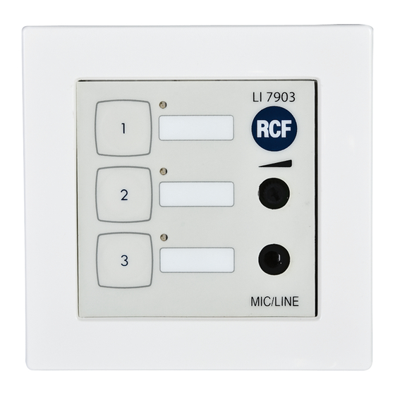
RCF S.P.A. THANKS YOU FOR PURCHASING THIS PRODUCT, WHICH HAS BEEN DESIGNED TO GUARANTEE RELIABILITY AND HIGH PERFORMANCE. 1. DESCRIPTION This remote control has 3 programmable function buttons (each with a LED) and can be used to connect and route a local microphone or a music source through the front panel audio input (3.5 mm TRS jack). -
Page 6: Address Setting
3. ADDRESS SETTING Set the device address using S1 dip-switches (1 to 5) on the front printed circuit board, according to the following table: 1 2 3 4 5 6 DIGITAL ADDRESS TABLE DIP-SWITCH ADDRESS... -
Page 7: Mic/Line Input 'Phantom' Power Supply
4. MIC/LINE INPUT ‘PHANTOM’ POWER SUPPLY S1 dip-switch no.6 activates the MIC/LINE input ‘Phantom’ power supply (needed for electret microphones). DIP 6 MIC input ‘Phantom’ power supply is disabled MIC input ‘Phantom’ power supply is on (+ 24 V dc) 5. -
Page 8: Mounting
7. MOUNTING Screw the LI 7903 remote control with its fastening plate to its wall box Connect its front panel to the 8-pin connector on the PCB (note: make sure the DXT 7000 system is off before proceeding). Press its front panel into the fastening plate in a way that its clips (on the upper and lower edges) lock it. - Page 9 MESSAGE PAGING A single or continuous message can be sent to an assigned zone. If a chime is set, the LED of the relevant button will rapidly blink during the chime play. During the message play, the LED blinks slowly. Single messages will terminate automatically.
-
Page 10: Avvertenze Per La Sicurezza
8. La RCF S.p.A. raccomanda vivamente che l’installazione di questo prodotto sia eseguita solamente da installatori professionali qualificati (oppure da ditte specializzate) in grado di farla correttamente e certificarla in accordo con le normative vigenti. Tutto il sistema audio dovrà... -
Page 11: Descrizione
RCF S.P.A. VI RINGRAZIA PER L’ACQUISTO DI QUESTO PRODOTTO, REALIZZATO IN MODO DA GARANTIRNE L’AFFIDABILITÀ E PRESTAZIONI ELEVATE. 1. DESCRIZIONE Il controllo remoto LI 7903 ha 3 tasti funzione programmabili (ciascuno con un LED di segnalazione) e può essere usato per collegare un microfono od una sorgente musicale locale tramite l’ingresso (jack TRS 3,5 mm) sul pannello... -
Page 12: Impostazione Dell'indirizzo
3. IMPOSTAZIONE DELL’INDIRIZZO Impostare l’indirizzo del controllo remoto tramite i microinterruttori S1 (“dip-switch” da 1 a 5) sul circuito stampato anteriore secondo la seguente tabella: 1 2 3 4 5 6 TABELLA DEGLI INDIRIZZI DIP-SWITCH INDIRIZZO... -
Page 13: Alimentazione All'ingresso Mic/Line
4. ALIMENTAZIONE ALL’INGRESSO MIC/LINE Il microinterruttore 6 del gruppo S1 attiva l’alimentazione “Phantom” all’ingresso MIC/LINE (necessaria per i microfoni ad elettrete). DIP 6 nessuna alimentazione “Phantom” alimentazione “Phantom” inserita (+ 24 V c.c.) 5. INGRESSO MIC/LINE Sul pannello frontale è presente un ingresso audio mono microfonico o di linea (jack TRS 3,5 mm). -
Page 14: Installazione
7. INSTALLAZIONE Fissare il controllo remoto LI 7903 alla sua scatola da parete. Collegare il pannello frontale al connettore ad 8 poli del circuito stampato (nota: assicurarsi che il sistema DXT 7000 sia spento prima di procedere). Inserire e premere il pannello frontale nel telaio in modo che le clip (sia sul bordo superiore, sia su quello inferiore) lo fissino. - Page 15 MESSAGGI REGISTRATI Un messaggio può essere inviato (una sola volta o continuamente) ad una zona assegnata. Se il tono di preavviso è previsto, il LED del tasto lampeggia velocemente durante la sua diffusione. Durante la riproduzione del messaggio, il LED lampeggia lentamente. I messaggi inviati una sola volta comportano l’autodisattivazione al termine;...
- Page 16 RCF SpA: Via Raffaello, 13 - 42124 Reggio Emilia > Italy tel. +39 0522 274411 - fax +39 0522 274484 - e-mail: rcfservice@rcf.it...
Need help?
Do you have a question about the DXT7000 and is the answer not in the manual?
Questions and answers