Table of Contents
Advertisement
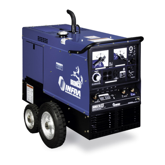
BRONCO 255K XD
OWNER´S MANUAL
PROCESS
STICK (SMAW)
MIG (GMAW)
TIG (GTAW)
DESCRIPTION
CONSTANT CURRENT/CONSTANT VOLTAGE
CC
CV
(CC / CV)
WELDING GENERATORTYPE:AC/DC.
VISIT OUR W EBSITE AT: www.comparcwelders.ca
GIVE THIS MANUALTO THE OPERATOR
ENGINE DRIVEN WELDING GENERATOR
OWNER´S MANUAL
T M
PM1323 REV. 0
E: 21-01-2021
304-855
Advertisement
Table of Contents

Related Manuals for Comparc BRONCO 255K XD


Summary of Contents for Comparc BRONCO 255K XD
- Page 1 PM1323 REV. 0 E: 21-01-2021 BRONCO 255K XD ENGINE DRIVEN WELDING GENERATOR OWNER´S MANUAL PROCESS STICK (SMAW) MIG (GMAW) TIG (GTAW) DESCRIPTION CONSTANT CURRENT/CONSTANT VOLTAGE (CC / CV) WELDING GENERATORTYPE:AC/DC. VISIT OUR W EBSITE AT: www.comparcwelders.ca GIVE THIS MANUALTO THE OPERATOR OWNER´S MANUAL...
-
Page 2: Table Of Contents
TABLE OF CONTENS ARC ELECTRIC WELDING SAFETY PRECAUTIONS ..........................i SECTION 1 -- SAFETY SIGNAL WORDS ...............................1 1 - 2 Symbol usage and definition ..............................1 SECTION 2 SPECIFICATIONS ................................2 2 - 1 Specifications ....................................2 2 - 2 Fuel Consumption Curves ..............................2 2 - 3 AC Auxiliary Power ...................................2 2 - 4 Volts - Amperes Curves ................................3 2 - 5 Duty Cylce ....................................3... -
Page 3: Arc Electric Welding Safety Precautions
ARC WELDING SAFETY PRECAUTIONS ARC WELDING can be hazardous. WARNING - DANGER! - Indicates a hazardous situation which, if not avoided, will result in death or serious injury. The possible hazards are shown in the adjoining symbols or explained in the text - Indicates a hazardous situation which, if not avoided, could result in death or serious injury. - Page 4 WELDING can cause fire or explosion. 4.- Be alert that welding sparks and hot materials from welding can easily go through small cracks and openings to adjacent areas. 5.- Watch for fire, and keep a fire extinguisher nearby. Sparks and spatter fly off from the welding arc. The 6.- Be aware that welding on a ceiling, floor, bulkhead, or partition can flying sparks and hot metal, weld spatter, hot workpiece, cause fire on the hidden side.
- Page 5 ST EAM AND PRESSURIZED HOT 1.- Do not remove radiator cap when engine is hot. Allow engine to cool. COOLANT can burn face, eyes, and skin. 2.- Wear gloves and put a rag over cap area when removing cap. The coolant in the radiator can be very hot and under 3.- Allow pressure to escape before completely removing cap.
-
Page 6: Section 1 -- Safety Signal Words
SECTION 1 - SAFETY SIGNALS AND SYMBOLS 1-1 Safety signal words. The following safety alert symbol and signal words are used throughout this manual to call attention to and identify different levels of hazard and special instructions. WARNING statements identify procedures or practices which must be followed to WARNING avoid seriuos personal injury or loss of life. -
Page 7: Section 2 Specifications
SECTION 2 SPECIFICATIONS 2.1 SPECIFICATIONS WELD RATED WELD AUXILIARY FUEL TANK M AX . ENGINE OUTPUT OUTPUT PROCESS POWER CAPACIT Y O. C. V. RANGE 250A, 25V KOHLER 10000 W continuous AC/CC 45-250 A 100% DUTY CH730 CYCLE AIR COOLING 11000 W MAX 40 LTS 250A, 25V... -
Page 8: Duty Cylce
2-4 VOLT-AMPERE CURVES The volt-ampere curves show the minimum and maximum voltage and amperage output capabilities of the welding power source. Curves of all other settings are between the curves shown. A: CV/DC MODE MAX. 20-28 MAX. 17-22 B: CC/DC MODE MIN. -
Page 9: Section 3 Installation
SECTION 3 INSTALLATION 3-1 SELECTING A LOCATION & MOVING WELDING SOURCE. READ SAFETY BLOCKS at beginning of CAUTION manual before proceeding. 1.- Keep free space 457mm (18") around the unit for a good air LEFT REAR flow. 2.- Lifting eye. Use only for lif t the unit. -
Page 10: Battery Connections
3-4 BATTERY CONNECTIONS 1 Ignition switch. 2 Screw. 3 Battery Box Door. 4 Negative Terminal(-) 5 Positive Terminal (+) Be sure ignition switch is on "OFF" position. To connect battery: connect negative cable last. To disconnect battery: disconnect negative cable first. TOOLS NEEDED 9.5mm (3/8") 12.7mm (1/2") -
Page 11: Connecting To Ground The Welding Generator
3-6 CONNECTING TO GROUND THE WELDING GENERATOR 1. Generator Grounding Terminal. 2. Use 10 AW G cable size or large, to grounding F-0351 F-0352 This point is connected to REV. A REV. A welding generator structure. GROUND TOOLS NEEDED 11.1mm (7/16") CONNECTING OUTPUT TERMINALS WARNING READ SAFETY BLOCKS at beginning of manual before proceeding. -
Page 12: Selecting & Preparing Weld Output Cables
SELECTING & PREPARING WELD OUTPUT CABLES 1.- Weld circuit cable T o s el ec t wel d c ab l e s i z e, p r oc eed as f ol lows : a) Calculate total cable length in weld circuit. Determine maximum welding current and duty cycle. -
Page 13: Coarse Range Selector
CAUTION ARCING can damage switch.Do not change AC/DC polarity switch position while welding.Arcing inside switch can damage contact, causing switch to fail. 4-2 WELD PROCESS Weld process selector switch AC/DC Use switch to select type of weld output. For direct current electrode negative use STRAIG THPOLARITY position. -
Page 14: Amperage/Voltage Fine Control
4-5 AMPERAGE / VOLTAGE FINE CONTROL 1.- FINE CONTROL (AMPERAGE/ VOLTAGE) Use control to set weld amperage or voltage within the range selected by the coarse range selector. The scale is a percentage of the range selected non an actual amperage or voltage value. -
Page 15: Mig Welding Outputs And Settings Controls
4-7 MIG WELDING OUTPUTS AND SETTINGS CONTROLS 1.- WELD PROCESS. Set this selector in REVERSE POLARITY. 2.- COARSE RANGE. Set this selector in HIGH RANGE or LOW RANGE according to your needs. 3.- CIRCUIT BREAKER CB6. Protects to 24 Vac winding agains ov erloads on receptacle RC4. 4- RECEPTACLE RMT 14 (RC4) Insert the conector of the wire f eeder, and tighten firmly. - Page 16 SECUENCE TO WELD WITH SHIELDED METAL ( SMAW ) Turn On The Install & Connect Select the W ear Saf ety Start the Engine Set Controls Au xi li ar y the Equipment Electrode Equipment Equipment Insert Electrode On Begin to W eld Electrode-Holder SECUENCE TO WELD W ITH FLUX CORED ELECTRODE ( FCAW ) Install &...
-
Page 17: Section 5 Auxiliary Power
SECTION 5 AUXILIARY POWER READ SAFETY BLOCKS at beginning CAUTION of manual before proceeding. 5-1 RECEPTACLES T he auxiliary fo rc e d ec reases as t he w eld in g cu rren t in c reases. Set the fin tuning for maximun R1 in 10 auxiliary output. 1.- Receptacle of 120 V, 20 Amp (RC1) 2.- Receptacle of 120 V, 20 Amp (RC2) RC1 and RC2 to 60 Hz single phase power supply . -
Page 18: W Iring Instructions For Ac Plugs
120V loads, each duplex receptacle shares a load with one half of the 120/240V receptacle. Combined load of a duplex receptacle and corresponding half of 120/240V recepacle cannot exceed 30 amperes. T OOLS NEEDED 5-3. ELECTRICAL APPLIANCES USED WITH BRONCO 255K XD ELECTRICAL DEVICES TYPE ATTENTION COMMON... -
Page 19: Routine Manitenance
SECTION 6 MAINTENANCE & TROUBLESHOOTING SEE SAFETY SIGNAL AT THE BEGINING THIS WARNING M A NU A L CAUTION FIRST 5 HOURS The first oil change must be to make when the first 5 hours of work are finished Change ROUTINE MAINTENANCE. -
Page 20: Engine Maintenance
ENGINE MAINTENANCE See engine manual for complete engine care. Give engine specifications and serial number when ordering parts. Check daily oil level Recomended oil ..SAE 30 Clasificatión SF, SG, SH, SJ Oil change First oil change..First 5 hours of work Dirty conditions.... -
Page 21: Air Filter Maintenance
6-3 AIR FILTER MAINTENANCE Stop engine. Do not work the engine without air filter. 1. Foam Rubber element. W ash the foam Rubber element with water and soap. Dry completely with air. Impregnate the foam rubber element with SAE 30 oil and wring the oil excess. -
Page 22: Connecting Or Replacing The Battery
6-5 CONNECTING OR REPLACING THE BATTERY WARNING Read the section at the begnning of the manual and then pr oc eed. If the machine does not have the strength to start, check the battery voltage as follows: 1 Ignition switch. Set the switch in position "off"... -
Page 23: Adjustment Engine Speed
ADJUSTMENT ENGINE SPEED WARNING READ SAFETY BLOCKS at beginning of manual before proceeding. Engine speed have been factory set and not should require adjustment. After tuning engine check engine speed with a tachometer.See table for proper no load speeds. If is necesary, adjustment speed as f ollow: 220 0+/- 100r pm 37+/-1.5... -
Page 24: Engine Electric System Protection
6-7 EXITATION WINDINGS PROTECTION WARNING READ SAFETY BLOCKS at beginning of manual before proceeding. 1.- Circuit breaker CB7 Protects the weld exitation winding from overload. If CB7 opens, weld output stops or is low. 2.- Circuit breaker CB8 Protects the generator power exitation winding from overload. -
Page 25: Troubleshootings
6-9 TROUBLESHOOTING READ SAFETY BLOCKS at beginning of manual bef ore WARNING proc eeding. TABLE 6-1 WELDING TROUBLE TROUBLE SOLUTION Check weld connections. Check control settings. Check and replace F1 if necessary. WELD OUTPUT. Contact your authorized sevice center for clean slip rings, and install new brushes, if necessary. - Page 26 TABLE 6-3 ENGINE TROUBLE. TROUBLE SOLUTION ENGINE DOES NOT START Check battery and engine charging system. Check fuel and oil levels. Check continuity of low oil pressure. ENGINE STARTS, BUT STOPS Check oil level. ENGINE Check continuity of low oil pressure shutdown switch S5 STOPS DURING NORMAL OPERATION.
-
Page 27: Section 7 Electrical Diagram
SECTION 7 ELECTRICAL DIAGRAM LOAD LOAD LINE LINE 50 B 50 B 50 A PM1323... -
Page 28: Section 8 Auxiliar Power Guide
SECTION 8 AUXILIARY POWER GUIDE WARNING READ SAFETY BLOCKS at beginning of manual before proceeding. 8-1 HOW MUCH POWER DOES EQUIPMENT REQUIRED? 1.- RESISTIVE LOAD. VOLTS 120 A light bulb is a resistive load and requires AMPS 4.5 a constant amount of power. 2.-NON-RESISTIVE LOAD. - Page 29 Ru nni ng St arti ng Ru nni ng St arti ng In dust ria ls M oto rs Rating Farm Equipment Rating W at ts . Wa tt s W at ts . Wa tt s Stock T ank De-Icer. 1000 1000 1/8 HP...
- Page 30 TABLE 7-2 SINGLE PHASE INDUCTION MOTOR STARTING REQUIREMENTS. CODE KVA/HP 10.0 11.2 12.5 14.0 1.- MOTOR RATING LABEL. AC MOTOR 2.- MOTOR START CODE. VOLTS 230 AMPS 2.5 Determine power required to start motor using CODE Table 7-2. Determine starting amperage requiered HP 1/4 1 PHASE as shown in Figure 7-4.
-
Page 31: Section 9 Parts List
SECTION 9 PARTS LIST LIST 9 -1 GENERAL ASSEMBLY ITEM PART No. I.D. D E S C R I P T I O N QUANTITY Fig. B. Panel front PT3603 Panel, side Right. PC3301 Panel cover. PT3604 Panel, side Left. PE0078 Gasket. - Page 32 FIG. 9 -1 GENERAL ASSEMBLIY PM1323...
- Page 33 LIST A GENERATOR ASSEMBLY ITEM PART No. I.D. D E S C R I P T I O N QUANTITY PA1003 engine, adapter. PV0240 Fan aluminium. MC01204 Bearing, secure. PT1642 Cover, front.. MB00073 Bearing. Brushes, assembly: MC09879 Brushes. MP08280 Brushes holder. MT07724 Brushes cover PS0921...
- Page 34 LIST B FRONT PANEL ASSEMBLY ITEM PART No. I.D. D E S C R I P T I O N QUANTITY MR08741 Rheostat 100 w, 10. PP4301 Nameplate, upper. PF0871 Panel front. PC1475 Switch, range. PC0918 Switch, polarity. MR09889 RC1,RC2 Receptacle, duplex 120 Vac, 20Amp MC10319 CB1,CB2...
- Page 35 PM1323...
- Page 36 LIST BAFFLE ASSEMBLY ITEM PART No. I.D. D E S C R I P T I O N QUANTITY MC09223 Capacitor, electrolitic 1100mF, 150V. PA0380 Capacitor, holder. PB1738 Baffle central. MR09972 Adjustable Resistor 225 W, 5 . PR0650 Rectifier. Consisting of: PP2659 Rectifier Positive plate.
- Page 37 CROSSFIRE ® LIMITED WARRANTY Effective April 14, 2018 (This limited warranty supercedes all prior warranties and is exclusive with no other warranties or garuntees implied.) This warranty applies to the original purchaser and is 6. Voiding Warranty subject to the terms and conditions listed below. This The limited warranty is void if the Crossfire product has Limited Warranty is for new equipment sold after the been repaired, changed, or modified by anyone other then...
- Page 38 NOTES...
- Page 39 SERVICE CENTER MAP CANADA LTD 325 Healey Road, Unit 1, Bolton, ON L7E 5C1 Canada Phone: (905) 951-2788 Toll Free: (800) 757-4445 Fax: (905) 951-6256...
Need help?
Do you have a question about the BRONCO 255K XD and is the answer not in the manual?
Questions and answers