Table of Contents
Troubleshooting

Related Manuals for Comparc S 604 MT


Summary of Contents for Comparc S 604 MT
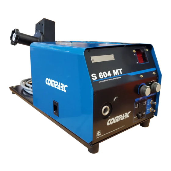
- Page 1 PM1326REV. 3 E. 21-01-2021 R: 29-09-2021 OWNER´S MANUAL S 604 MT 24 V CONSTANT SPEED PROCESSES MIG (GMAW) & FCAW. VISIT OUR W EBSITE AT: www.siisa-infra.com.mx GIVE THIS MANUALTO THE OPERATOR OWNER´S MANUAL 3 09 - 14 0...
-
Page 2: Table Of Contents
TABLE OF CONTENTS SECTION 1 -- ARC WELDING SAFETY PRECAUTIONS ............ i SECTION 2 -- SAFETY INFORMATION ................1 SECTION 3 - SPECIFICATION ..................... 1 3-1. Rating Label Location ....................... 1 3-2. Specifications ........................... 1 3-3. Environmental Specification ..................... 1 SECTION 4 - INSTALLATION .................... - Page 3 SECTION 1 - SAFETY PRECAUTIONS - READ BEFORE USING ARC WELDING can be hazardous. WARNING - DANGER! - Indicates a hazardous situation which, if not avoided, will result in death or serious injury. The possible hazards are shown in the adjoining symbols or explained in the text - Indicates a hazardous situation which, if not avoided, could result in death or serious injury.
- Page 4 WELDING can cause fire or explosion. 4.- Be alert that welding sparks and hot materials from welding can easily go through small cracks and openings to adjacent areas. 5.- Watch for fire, and keep a fire extinguisher nearby. Sparks and spatter fly off from the welding arc. The 6.- Be aware that welding on a ceiling, floor, bulkhead, or partition can flying sparks and hot metal, weld spatter, hot workpiece, cause fire on the hidden side.
- Page 5 ST EAM AND PRESSURIZED HOT 1.- Do not remove radiator cap when engine is hot. Allow engine to cool. COOLANT can burn face, eyes, and skin. 2.- Wear gloves and put a rag over cap area when removing cap. The coolant in the radiator can be very hot and under 3.- Allow pressure to escape before completely removing cap.
-
Page 6: Section 2 - Safety Information
SECTION 2 - SAFETY INFORMATION The following safety alert symbol and signal words are used throughout this manual to call attention to and identify different levels of hazard and special instructions. WARNING statements identify procedures or practices which must be followed WARNING to avoid seriuos personal injury or loss of life. -
Page 7: Section 4 Installation
SECTION 4 INSTALLATION 4-1. SITE SELECTION SEE SAFETY RULES AT THE BEGG INING O F M ANUAL CAUTION BEFORE PROCEED 1.- WIRE FEEDER. Do not put feeder were welding wire hits cilynder. 2.- LIFTING EYE. 3.- RUBBER SUPPORTS(UNDER WIRE FEEDER). 4.- INSTALLATION SLOT. -
Page 8: Connecting Welding Gun, Voltaje Clamp And Weld Cable
4-3. CONNECTING WELDING GUN, VOLTAGE CLAMP AND WELD CABLE 1.- REMOTE 14 CABLE 2.- SHIELDING GAS VALVE INLET 3.- FUSE F1 4.- SWITCH S1 5.- WIRE FEED INLET 6.- CABLE TO WELDING POWER SOURCE 4-4. CONNECTING 14-PIN PLUG Socket INFORMATION REMOTE-14 24 V a.c. -
Page 9: Installing Welding Gun
4-5. INSTALLING WELDING GUN Turn Off wire feeder and welding power source. Turn off wire feeder or welding power source before handling or moving clamp. 1 Fix Knob 2 Gun Locking Tab 3 Power Pin groove 4 Gun Connection End Installing gun with gun locking tab in place system Loosen power clamp knob to allow power pin... -
Page 10: Spool Wire Installation
4-6. SPOOL WIRE INSTALLATION. For 8" and 12" (standard) wire spools turn unit off and disconnect it. 1.- Hub spool. 2.- Pin of Hub spool. 3.- Wire spool / Reel. 4.- Hud spool cap. Turn the hub spool cap clockwise and remove it. - Page 11 4-8. WELDING WIRE INSTALLATION - CONTINUATION Hold Wire Tightly to Keep It From Unraveling Pull and Hold Wire, Cut Push Wire Thru Guides Into Open Pressure Assembly Off End. Gun; Continue to Hold Wire Turn On Welding Power Source The Output Contactor Switch Must POWER Be in Next Position: Close and Latch Pressure...
-
Page 12: Section 5 Operation
SECTION 5 OPERATION SEE SAFETY SIGNAL AT THE BEGINING CAUTION THIS M ANUAL 5-1. CONTROLS REMOTE VOLTAGE ADJUSTMENT CONTROL WIRE SPEED CONTROL PURGE BUTTON BURN BACK TIME JOG BUTTON GUN TRIGGER TRIGGER MODE RECEPTACLE SELECTOR FIGURE 5-1 CONTROLS 1- Insulating Gloves. 2- Safety Glasses With Side Shields. - Page 13 1.- WIRE SPEED CONTROL. Use this control to select wire feed speed in speed ranges. Turn in clock wise to increase speed. The numbers is a percentage respect a maximun rated speed (900ipm) FIGURE 5-5 WIRE SPEED CONTROL BURNBACK BURNBACK Use control to adjust the time that the welding wire is energized after wire feeding stops.
-
Page 14: Section 6 - Maintenance & Troubleshooting
1- DIGITAL VOLTMETER. It shows the output terminals voltage (in Volts) of the machine, but not necessarily the arc voltage, due to the resistance of the weld cables, loose connections, etc. 2- DIGITAL AM METER. It shows the weld current value in Amperes. REMOTE VOLTAGE ADJUSTMENT Use this control to set the arc voltage. -
Page 15: Overload Protection
6-3. OVERLOAD PROTECTION. WARNING SEE SAFETY SIGNAL AT THE BEGINING THIS M ANUAL DISCONNECT and turn off wire feeder and power source BEFORE proceed. INAPPROPIATE FUSES can damage unit. Be sure to POWER select correct fuse size and capacity according amperage used. -
Page 16: Section 7 - Electrical Diagrams
SECTION 7 ELECTRICAL DIAGRAM. PM1326... -
Page 17: Section 8 Parts List
SECTION 8 PARTS LIST List 7-1 Main Assembly D E S C R I P T I O N ITEM PART No QUANTITY FIG. 7-2 Control Box. PP3658 Hub Reel PT3623 Support, arm MR 01520 Rubber, support 1-1/8" PB2389 Chasis FIG 7-2 Figure 7-1 Main assembly PM1326... -
Page 18: List Control Box
List 7-2 Control Box. Item No. Part No. I.D. Description Quantiy PC3133 Base box MV00768 Solenoid Valve PT1071 Retaining nut, Gas solenoid valve (not illustrated) Overload Protection. Consisting of: MF02310 Fuse, 10A MP00014 Fuse Holder, 15A PT3636 PCB Control MI01178 Power Switch MI00665 S2,S3... -
Page 19: Part List Of Feeder Mechanism Of Wire
LIST 7-3 Part List of Feeder Mechanism of Wire IT. No PART No. DESCRIPTION QUANTITY PB2324 Feed plate For Gun Locking Tab ----- Roll (Ask to your distributor) MB06013R Fixing arm compl. CWF400-600 MG02270 Intermediate guide MF02408R Shaft D6X35 MA04084R Retaining ring ME02416R Gas hose... - Page 20 NOTES...
- Page 21 WARRANTY POLICY 2°.- SOLDADORAS INDUSTRIALES INFRA S.A. DE C.V. warranty UNIFORM WARRANTY FOR SIISA MACHINES. will be F.O.B. Factory at Naucalpan México, or F.O.B. at an authorized service facility as determined by manufacturer. Therefore no compensation SOLDADORAS INDUSTRIALES INFRA, S.A. DE C.V. (SIISA), or reimbursement for transportation costs of any kind will be allowed.
- Page 22 NOTES...
- Page 23 SERVICE CENTER MAP CANADA LTD 325 Healey Road, Unit 1, Bolton, ON L7E 5C1 Canada Phone: (905) 951-2788 Toll Free: (800) 757-4445 Fax: (905) 951-6256...
- Page 24 SOLDADORAS INDUSTRIALES INFRA, S.A. DE C.V. Plásticos No. 17 Col. San Francisco Cuautlalpan C.P. 53560 Naucalpan de Juárez Edo. de México Phone: (52) 53-58-41-83 53-58-87-74 53-58-44-00 Fax: (52) 55-76-23-58...
Need help?
Do you have a question about the S 604 MT and is the answer not in the manual?
Questions and answers