Table of Contents
Advertisement
Advertisement
Table of Contents
Troubleshooting

Related Manuals for Comparc ALPHA TIG 252 - DP


Summary of Contents for Comparc ALPHA TIG 252 - DP
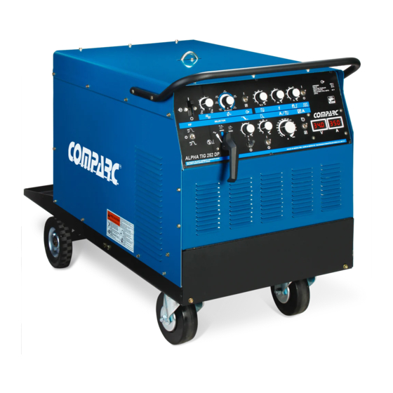
- Page 1 PM1328 REV. 0 E: 21-01-2021 OWNER´S MANUAL ALPHA TIG 252 - DP AC/DC ARC WELDING POWER SOURCE PROCESSES STICK PROCESS (SMAW) TIG PROCESS (GTAW) DESCRIPTION OUTPUT TYPE: AC/DC VISIT OUR W EBSITE AT: www.comparcwelders.ca GIVE THIS MANUALTO THE OPERATOR OWNER´S MANUAL...
-
Page 2: Table Of Contents
TABLE OF CONTENTS SECTION 1 - SAFETY PRECAUTIONS - READ BEFORE USING ..........i SECTION 1 SAFETY SIGNAL WORDS ................. 1 SECTION 2. ESPECIFICATIONS ....................1 ................... 2 - 1. VOLT-AMPERE CURVES 2 - 2. DUTY CYCLE..........................SECTION 3 -- INSTALLATION ....................2 3 - 1. -
Page 3: Section 1 - Safety Precautions - Read Before Using
SECTION 1 - SAFETY PRECAUTIONS - READ BEFORE USING ARC WELDING can be hazardous. WARNING - DANGER! - Indicates a hazardous situation which, if not avoided, will result in death or serious injury. The possible hazards are shown in the adjoining symbols or explained in the text - Indicates a hazardous situation which, if not avoided, could result in death or serious injury. - Page 4 WELDING can cause fire or explosion. 4.- Be alert that welding sparks and hot materials from welding can easily go through small cracks and openings to adjacent areas. 5.- Watch for fire, and keep a fire extinguisher nearby. Sparks and spatter fly off from the welding arc. The 6.- Be aware that welding on a ceiling, floor, bulkhead, or partition can flying sparks and hot metal, weld spatter, hot workpiece, cause fire on the hidden side.
- Page 5 ST EAM AND PRESSURIZED HOT 1.- Do not remove radiator cap when engine is hot. Allow engine to cool. COOLANT can burn face, eyes, and skin. 2.- Wear gloves and put a rag over cap area when removing cap. The coolant in the radiator can be very hot and under 3.- Allow pressure to escape before completely removing cap.
-
Page 7: Section 1 Safety Signal Words
SECTION 1 SAFETY SIGNAL WORDS The following safety alert symbol and signal words are used throughout this manual to call attention to and identify different levels of hazard and special instructions. WARNING statements identify procedures or practices which must be followed to WARNING avoid serious personal injury or loss of life. -
Page 8: Duty Cycle
2-2 DUTY CYCLE. WELDING LONGER THAN RATED DUTY CYCLE can damage unit or gun WARNING and void warranty.Do not weld at rated load longer than shown below. Rated Output Definition: Duty Cycle is percentage of 10 minutes that unit or electrode holder can weld at rated load without overheating. -
Page 9: Selecting And Preparing Weld Output Cables
3-2 SELECTING AND PREPARING WELD OUTPUT CABLES. 1.- Weld Output Cable. Determine total cable length in weld circuit and maximum welding Tools amperes. Use Table 3-1 to select proper cable Needed size. Use shortest cables possible. Do not use damaged cables. 3/4"... -
Page 10: Connecting Output Terminals
3-4 CONNECTING OUTPUT TERMINALS. WARNING ELECTRIC SHOCK can kill. Location Of 1.- Work Weld Output Terminal. Terminals 2.- Electrode Weld Output Terminal. 3.- Access Door. Tools Needed Connect cables as shown. Close and secure access door. 3/4" (19 m m ) SMAW Connections GTAW Connections Work... -
Page 11: Remote 14 Connections
3-6 REMOTE 14 CONNECTIONS. SOCKET* SOCKET INFORMATION. REMOTE 14 OUTPUT 24 Volts AC. (CONTACTOR) Contact Closure to A completes 24 VAC contactor control circuit. +10VDC Output to remote control Remote control circuit common. AMPERAGE 0 to +10 VDC input command signal from remote control Chassis common. -
Page 12: Shielding Gas Connection
3-9 SHIELDING GAS CONNECTION. CYLINDER can explode if damaged. WARNING BUILDUP OF SHIELDING GAS can harm healt or kill. Obtain gas cylinder and chain to running gear, wall, or other stationary support so cylinder cannot fall and break off valve. 1.- CAP. -
Page 13: Section 4 -- Function Of Controls
SECTION FUNCTION OF CONTROLS SEE SAFETY SIGNAL AT THE BEGINING CAUTION THIS M ANUAL 4-1. CONTROLS OF WELDING POWER SOURCE AC BALANCE POSTFLOW OUTPUT POWER CURRENT BACKUP CONTROL TIME CONTROL (CONTACTOR) PULSE PER SWITCH CONTROL SWITCH SECOND CONTROL HIGH FREQUENCY PERCENTAGE SWITCH TIME PULSE... - Page 14 To use post flow time POST-FLOW TIME circuit POSTFLOW TIME Use control to set the length of time gas flows PANEL after the welding stops. Adjust time according to size of tungsten electrode in torch. REMOTE Connect Remote Device Figure 4-4 Postflow Time Control 1.- HIGH FREQUENCY SWITCH.
- Page 15 Set Switches Set Output Set Control SELECTOR DC REVERSE POLARITY STRAIGHT POLARITY PANEL REMOTE REMOTE OUTPUT CONTACTOR Min= 0 A DC 1.- Fingertip Control 2.- Remote Foot Control. Max= 200 A DC Min=0 A DC 3.- Remote Hand Control Percentege Of Range=50% Adjust Remote Control Output=100 A DC (50% of 0 to 200) Figure 4-8 Example Of Combination Remote Amperage Control.
-
Page 16: 1A. Pulser Controls
To use crater time circuit 1.- CRATER TIME CONTROL Use control to set time to taper weld ouput from setting of the amperage adjustment control to PANEL the minimum of the unit. 2.- CRATER TIME SWITCH REMOTE ON- Provides Crater time OFF- Provides No Crater time REMOTE Place switch in the OFF position for SMAW. - Page 17 The PULSES PER SECOND control provides a means of selecting the pulse selecting. Rotating the control clockwise increases the pulse frequency. The scale is calibrated from 0.5 to 20 pulses per second. IMPORTANT: The PULSES PER SECOND control may be adjusted while welding. RANGE SELECTION: The PULSER CIRCUIT BOARD has an internal jumper for selecting the desired range for the PUL-...
-
Page 18: What Is Pulsing
4-3 WHAT IS PULSING? Pulsing refers to the alternate raising and lowering of the weld output at a periodic rate.(Ver Fig. 4-16). The highest value is called peak amperage, and that is the pulse, heats the molten weld puddle, the lowest value is commonly called background amperage and allows a degree of cooling molten weld puddle. -
Page 19: Section 5 -- Maintenance & Troubleshooting
1.- SHIELDING GAS METAL. 2.- VALVE. 3.- FINGER TIP CONTTOL. 4.-FOOT CONTROL. Open valve on cylinder just before welding. Finger tip control, or foot control turns weld output and gas flow on and off. Close valve on cylinder when finished welding. Figure 4-17 Shielding Gas. -
Page 20: Troubleshooting
TROUBLESHOOTING. CAUSE TROUBLE REMEDY Increase time settings of post-flow time control (See Gas shutting off too quickly after end of weld. figure 4-11). Loose gas fittings on regulator or gas line. This Check and tighten all gas fittings. will siphon oxygen into the weld zone. Tungsten electrode oxidizing and Insuficient gas flow. -
Page 21: Overload Protection
OVERLOAD PROTECTION. ELECTRIC SHOCK can kull. WARNING HOT PARTS can cause severe burns. Disconnect Unit BEFORE inspection unit. 1.- CIRCUIT BREAKER CB1. CB1 protects unit from overload in 120 Volts receptacle. Reset CB1 if necessary. Reinstall Top Befeore Operation Unit. Figure 5-1 Overload Protection. -
Page 22: Section 6. Electrical Diagram
SECTION 6. ELECTRICAL DIAGRAM... -
Page 23: Section 7. Parts List
SECTION 7. PARTS LIST ITEM No. PART No. I.D. DESCRIPTON QUANTITY Fig. "A" PANEL, front assy. PC1397 … … .. BASE, chassis. PT3608 TRANSFORMER, main. consisting of: PB2383 … … .. TRANSFORMER, coil PN0149 … … .. TRANSFORMER, core. PC1732 …... - Page 24 FIGURE 7-1. GENERAL ASSEMBLY...
- Page 25 7-2 FRONT ASSEMBLY. ITEM PART No. I.D. DESCRIPTION QUANTITY PT 0923 TERMINAL, pwr output. PF 0703 PANEL, front. MM04109 METERS Red Filter Plate MC 10192 CIRCUIT BREAKER 10 A. 250V. MR 02583 RC14 RECEPTACLE, 14 pins. MR 00521 RECEPTACLE, duplex 120V. ----- ---- MI 00110...
- Page 26 7-3 HIGH FREQUENCY UNIT ASSEMBLY. ITEM I.D. PART No. DESCRIPTION QUANTITY MT 07003 TRANSFORMER, high frequency 115 - 3600 V PT 1565 HIGH FREQUENCY PANEL, left. PT 1567 HIGH FREQUENCY PANEL, cover. PT 1566 HIGH FREQUENCY PANEL, right. MR 01735 RESISTOR 10...
-
Page 27: Section 8 Tungsten Electrode
SECTION 8 TUNGSTEN ELECTRODE For more information, it consult to your distributor on the TIG process. NOTE Use clean gloves to prevent polution in the tungsten electrode. SELECTING TUNGSTEN ELECTRODE. TABLE 8-1 TUNGSTEN SIZE Argon Gas , Gas type - Polarity Electrode DC - Negative DC Positive... - Page 28 PREPARING TUNGSTEN. 1.- Tungsten electrode. 2.- Balled end Ball end of tungsten before welding by applying either an AC amperage slightly 1 1/2 TIM ES higher than what is recomended for a given ELECTRODE electrode diameter(see table 6-1) or a DC DIAM ETER alectrode positive amperage.
- Page 29 CROSSFIRE ® LIMITED WARRANTY Effective April 14, 2018 (This limited warranty supercedes all prior warranties and is exclusive with no other warranties or garuntees implied.) This warranty applies to the original purchaser and is 6. Voiding Warranty subject to the terms and conditions listed below. This The limited warranty is void if the Crossfire product has Limited Warranty is for new equipment sold after the been repaired, changed, or modified by anyone other then...
- Page 30 NOTES...
- Page 31 SERVICE CENTER MAP CANADA LTD 325 Healey Road, Unit 1, Bolton, ON L7E 5C1 Canada Phone: (905) 951-2788 Toll Free: (800) 757-4445 Fax: (905) 951-6256...
Need help?
Do you have a question about the ALPHA TIG 252 - DP and is the answer not in the manual?
Questions and answers