Table of Contents
Advertisement
Quick Links
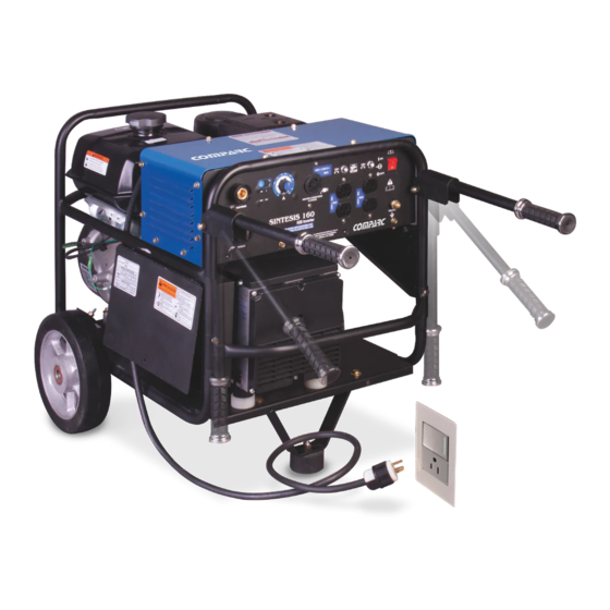
OWNER´S MANUAL
SINTESIS 160
CC - CD WELDER / 6200 WATTS GENERATOR
PROCESS
STICK (SMAW)
TIG (GTAW).
DESCRIPTION
OUTPUT TYPE :
CONSTANT CURRENT (CC).
DIRECT CURRENT ( CD)
VISIT OUR W EBSITE AT: www.siisa-infra.com.mx
GIVE THIS MANUALTO THE OPERATOR
OWNER´S MANUAL
T M
PM1401 REV. 0
E. 19-11-2021
304-878
Advertisement
Table of Contents
Troubleshooting

Related Manuals for Comparc SINTESIS 160


Summary of Contents for Comparc SINTESIS 160
- Page 1 PM1401 REV. 0 E. 19-11-2021 OWNER´S MANUAL SINTESIS 160 CC - CD WELDER / 6200 WATTS GENERATOR PROCESS STICK (SMAW) TIG (GTAW). DESCRIPTION OUTPUT TYPE : CONSTANT CURRENT (CC). DIRECT CURRENT ( CD) VISIT OUR W EBSITE AT: www.siisa-infra.com.mx GIVE THIS MANUALTO THE OPERATOR OWNER´S MANUAL...
-
Page 2: Table Of Contents
TABLE OF CONTENS ARC WELDING SAFETY PRECAUTIONS ......................i SECTION 1 SAFETY SIGNALS AND SYMBOLS ....................1 SECTION 2 SPECIFICATIONS ........................... 2 2 - 1 Specifications .............................. 2 2 - 2 Power supply electrical specifications ....................... 2 2 - 3 Volt-Amperes Curves ..........................3 2 - 4 Duty Cycle Curves ............................ -
Page 3: Arc Welding Safety Precautions
ARC WELDING SAFETY PRECAUTIONS ARC WELDING can be hazardous. WARNING - DANGER! - Indicates a hazardous situation which, if not avoided, will result in death or serious injury. The possible hazards are shown in the adjoining symbols or explained in the text - Indicates a hazardous situation which, if not avoided, could result in death or serious injury. - Page 4 WELDING can cause fire or explosion. 4.- Be alert that welding sparks and hot materials from welding can easily go through small cracks and openings to adjacent areas. 5.- Watch for fire, and keep a fire extinguisher nearby. Sparks and spatter fly off from the welding arc. The 6.- Be aware that welding on a ceiling, floor, bulkhead, or partition can flying sparks and hot metal, weld spatter, hot workpiece, cause fire on the hidden side.
- Page 5 ST EAM AND PRESSURIZED HOT 1.- Do not remove radiator cap when engine is hot. Allow engine to cool. COOLANT can burn face, eyes, and skin. 2.- Wear gloves and put a rag over cap area when removing cap. The coolant in the radiator can be very hot and under 3.- Allow pressure to escape before completely removing cap.
-
Page 6: Section 1 Safety Signals And Symbols
SECTION 1 - SAFETY SIGNALS AND SYMBOLS 1-1 Safety signal words. The following safety alert symbol and signal words are used throughout this manual to call attention to and identify different levels of hazard and special instructions. WARNING statements identify procedures or practices which must be followed to WARNING avoid seriuos personal injury or loss of life. -
Page 7: Section 2 Specifications
SECCION 2 SPECIFICATIONS 2-1. SPECIFICATIONS Generator power rating, Engine Power Type Fuel capacity Oil capacity Start 1 phase, 60 Hz 6500W max 1 Cylinder, Kohler CH 440 14 Hp @ 3600 rpm 0.980 l Electric Air cooled 6200W continuos weight, kg (lb): 105 (12.7) Ship, kg(lb): 120 (21.2) -
Page 8: Volt-Amperes Curves
2-3. VOLTS-AMPERES CURVES The volt-amperes curves show the minimum and maximum v ol tage and amperage output capabilities of the welding power source. Curves of other settings fall between the curves shown. ELECTRODE (220 V a.c.) ELECTRODE (120 V a.c.) MAX. -
Page 9: Auxiliary Power Curves
2-5 AC AUXILIARY POWER The ac generator power curves show the generator power available 1.0 F.P. in amperes at the 120 and 240 V receptacles. Amperes a 120 V a.c. Amperes a 240 V a.c. FIGURE 2-4 120/240 Vac AUXILIARY POWER OUTPUT SECTION 3 INSTALLATION 3.1 SELECTING A LOCATION WELDING SOURCE. -
Page 10: Engine Prestart Checks
3-2 ENGINE PRESTART CHECKS SEE SAFETY SIGNAL AT THE BEGINING THIS PRECAUCION M A NU A L Check the oil and fuel level daily. The motor must be cold 2 Fuel tank. Check fuel level before starting engine, add and the machine must be horizontally leveled. if necessary. -
Page 11: Grounding When Supplying A Building
3-4 GROUNDING WHEN SUPPLYING A BUILDING. 1.- EARTH TERMINAL OF TEAM. 2.- LANDING CABLE. Use an insulated copper cable # 10 AWG or greater. 3.- LANDING DEVICE. Ground the generator to a physical ground system (metal pipe, metal structure), when the generator supplies power to premises (houses, warehouses, etc.) with wiring system. -
Page 12: Selecting & Preparing Weld Output Cables
CABLE LENGTH FOR LOAD 240 Vac MAXIMUM PERMISSIBLE CABLE LENGTH IN Ft (m) Current Load FOR DIFFENENTS CALIBRES* (Amp.) (Watts) 4 AWG 6 AWG 8 AWG 10 AWG 12 AWG 14 AWG 1200 700 (213) 450 (137) 225 ( 69) 200 ( 61) 1680 800 (244) -
Page 13: Connection Of The Welding Power Source To The Engine Generator
3-7.CONNECTION OF THE WELDING POWER SOURCE TO THE ENGINE- GENERATOR. SEE SAFETY SIGNAL AT THE BEGINING THIS CAUTION M A NU A L The power supply is factory connected to the engine- generator by means of a half turn plug in the 250 V, 20 A. receptacle located in the side box of the chassis, see picture. -
Page 14: Supply Voltage 220 V A.c
3-10. SUPPLY VOLTAGE AT 220 V a.c. SEE SAFETY SIGNAL AT THE BEGINING THIS CAUTION M A NU A L THE EQUIPMENT MUST BE CONNECTED TO THE MAINS SUPPLY IN COMPLIANCE WITH CAUTION SAFETY STANDARDS AND IN CONDITIONS THAT DO NOT EXPOSE THE USER TO RISKS OR VOLTAGE DISCHARGES. -
Page 15: W Eld Cable Size
3-13. WELD CABLES SIZE. TOTAL CABLE (COPPER) LENGHT IN WELD CIRCUIT NOT EXCEEDING. * WELDING 150Ft (45 m) 200Ft (60 m) 250Ft (70 m) 300Ft (90 m) 350Ft (105 m) 100 Ft (30 m) or less 400Ft (120 m) 10 to 60% AMPERES 60 Thru 10 to 60%... -
Page 16: Section 5 Auxiliary Power Guide
SECTION 5 AUXILIARY POWER GUIDE WARNING READ SAFETY BLOCKS at beginning of manual before proceeding. 5-1 HOW MUCH POWER DOES EQUIPMENT REQUIRED? 1.- RESISTIVE LOAD. VOLTS 120 AMPS 4.5 A light bulb is a resistive load and requires a constant amount of power. 2.-NON-RESISTIVE LOAD. - Page 17 Ru nni ng St arti ng Ru nni ng St arti ng In dust ria ls M oto rs Rating Farm Equipment Rating W at ts . Wa tt s W at ts . Wa tt s Stock T ank De-Icer. 1000 1000 1/8 HP...
- Page 18 700W 200W 300W 500W POWER SINTESIS 160 examples of typical electrical appliances that can be connected to the generators considering power values at sea level. We recommend verifying the demand of your appliances starting power and continuous operation before connecting.
-
Page 19: Typical Connection For Emergency Plant
WARNING SEE SAFETY SIGNAL AT THE BEGINING THIS M A NU A L 5-3 TYPICAL CONNECTION FOR EMERGENCY PLANT. 1.- Utility meter. The customer shall supply the necessary equipment so that the 2.- Main protection switch. generator can be installed as an emergency plant. 3.- 2-pole 2-throw transfer swit- ch. -
Page 20: W Iring Of The 120 V.a.c. / 240 V A.c. Plug
5-5 WIRING OF THE 120 V.a.c. / 240 V. a.c. PLUG. Be sure to connect both 120V and 240V plugs as shown in the f igure, 1.- The 120 Vac. 15 Amp. plug should be connected in its flat terminals to the power supply (Phase and Neutral) and the round termi nal t o t he ground syst em of your equipment to avoid electric shocks. -
Page 21: Section 6 Maintenance And Troubleshooting
SECTION 6. MAINTENANCE AND TROUBLESHOOTING READ SAFETY BLOCKS at beginning of this manual before WARNING proc eeding. 6-1. ROUTINE MAINTENANCE CAUTION FIRST 5 HOURS Initial oil change should be performed after first twenty (20) hours of operation. Thereafter change oil every hundred (100) hours. Change Oil. -
Page 22: Routine Power Supply Maintenance
MAINTENANCE FIGURE 6-1 TABLE 6-1 ENGINE TROUBLE TROUBLE REMEDY Check fuel level The motor does not start. Check oil level Check that the fuel valve is open. Check the oil level. Verify that the oil level is adequate to prevent engine The motor stops during nor- damage. -
Page 23: Engine Maintenance
ENGINE MAINTENANCE KOHLER GASOLINE ENGINE See engine manual for complete engine care. Give engine specifications and serial number when ordering parts. Check Daily Recomended Oil ..... SAE 30 Service clasification SE, SF, SG Oil & Filter change First Change......20 hours *Dirty conditions.......25 hours or less *Normal conditions....50 hours Oil Capacity....1.5 qt (1.4 L) or 1.75 qt (1.6 L) w/filter change. -
Page 24: Section 7 Electrical Diagram
THE ELECTRICAL CONNECTION MUST BE ESTABLISHED 12 VOLT BETWEEN THE MOTOR-GENERATOR SET AND THE CHASSIS. STARTER OIL LEVEL IGN. SENSOR COIL CONTROL ALTERNATOR STATOR VOLT. REG. OIL LEVEL DE-0183 RECT. SENSOR YELLOW REV. 0 SINTESIS 160 FIGURE 7-1 ELECTRICAL DIAGRAM... -
Page 25: Section 8 Part List
SECTION 8 PARTS LIST LIST 8-1 GENERAL ASSEMBLY Ref. Part No. Description Quantity MM04445 ENGINE MG02210 GENERATOR PC2952 CHASSIS PM1173 HANDLE MM00197 HANDLE PR1089 REAR W HEELS (CONSTA DE:) MR10118 W HEEL MR00905 FLAT W HASER 5/8" MC01268 CHAVETA DE 1/8" PB1572 BASE FOR DAMPER SUPPORT PB1573... - Page 26 LIST 8-2 CABINET ASSEMBLY PART NUM REF. D E S C R I P T I O N PB2203 BASE OFF CABINETE ---------- ASSEMBLY PANEL FRONT PF0863 PANEL FRONT MC10508 CIRCUITBREAKER 40A MR09889 RECEPTACLE 120V MR00530 THREE-POLE RECEPTACLE MC11178 OUTPUT TERMINAL PT2541 CONTROL PCB MP08481...
- Page 27 LIST 8-3 MAIN CARD ASSEMBLY REF. PART NUM D E S C R I P T I O N PK0050 IGBT MT08647 MAIN TRANSFORMER MD01908 HEAT SINK MC11089 CAPACITOR MT08648 CURRENT TRANSFORMER MI01243 AUXILIARY INDUCER MR10159 RECTIFIER FIGURE 8.3 MAIN CARD ASSEMBLY...
- Page 28 SERVICE CENTER MAP CANADA LTD 325 Healey Road, Unit 1, Bolton, ON L7E 5C1 Canada Phone: (905) 951-2788 Toll Free: (800) 757-4445 Fax: (905) 951-6256...
Need help?
Do you have a question about the SINTESIS 160 and is the answer not in the manual?
Questions and answers