
AAON RZ Series Rooftop Unit Manuals
Manuals and User Guides for AAON RZ Series Rooftop Unit. We have 3 AAON RZ Series Rooftop Unit manuals available for free PDF download: Installation Operation & Maintenance

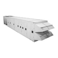
AAON RZ Series Installation Operation & Maintenance (136 pages)
Packaged Rooftop Units & Outdoor Air Handling Units
Brand: AAON
|
Category: Air Handlers
|
Size: 7 MB
Table of Contents
Advertisement

AAON RZ Series Installation Operation & Maintenance (96 pages)
Packaged Rooftop Units & Outdoor Air Handling Units
Brand: AAON
|
Category: Air Handlers
|
Size: 4 MB
Table of Contents
AAON RZ Series Installation Operation & Maintenance (112 pages)
Packaged Rooftop Units & Outdoor Air Handling Units
Brand: AAON
|
Category: Air Handlers
|
Size: 5 MB
Table of Contents
Advertisement
Advertisement