
Related Manuals for fann 415C


Summary of Contents for fann 415C
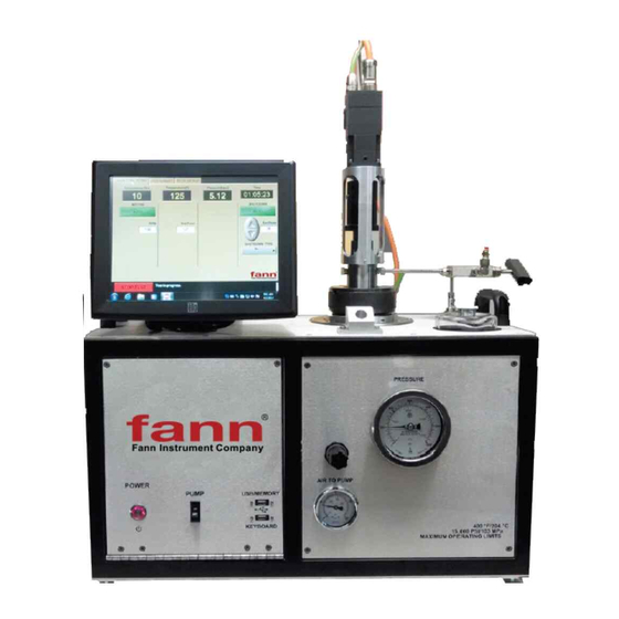
- Page 1 Model 415C & 415 SGS HPHT Pressurized Consistometer and Cement Consistometer with Gel Strength Analyzer Instruction Manual Manual No. D01669102, Revision A Instrument No. 102547776, 102538946 ©2019 Fann Instrument Company...
- Page 2 Printed in USA. The information contained in this document includes concepts, methods, and apparatus which may be covered by U.S. Patents. Fann Instrument Company reserves the right to make improvements in design, construction, and appearance of our products without prior notice.
-
Page 3: Table Of Contents
Model 415C & 415 SGS Instruction Manual Table of Contents Introduction ........................ 5 1.1 Model 415C ....................... 5 1.2 Model 415SGS ....................6 1.3 Document Conventions ..................7 Safety ......................... 8 2.1 Safe Pressurization .................... 8 2.2 Safe Heating ...................... 8 2.3 Safe Electrical Operation ................... - Page 4 Model 415C & 415SGS Instruction Manual 7.4 Removing Slurry Cup Plug from Pressure Vessel ........... 38 7.5 Slurry Removal ....................39 Maintenance and Troubleshooting ................41 8.1 Slurry Cup Bottom Removal and Reinstallation ..........41 8.2 Paddle Shaft and Paddle ................. 42 8.3 Slurry Cup Plug Disassembly and Reassembly ..........
-
Page 5: Introduction
Model 415C & 415SGS Instruction Manual Introduction Model 415C Model 415C pressurized consistometer is able to test cement slurries at temperatures up to 400ºF/204ºC and pressures to 15,000 psig / 103 MPa. The instrument is designed to perform thickening time tests in accordance with API specifications and recommended practices. -
Page 6: Model 415Sgs
Model 415C & 415SGS Instruction Manual Model 415SGS Model 415SGS combines thickening time and static gel strength testing into one compact, easy to use, simple to maintain unit. Model 415SGS represents the easiest to operate and most reliable static gel strength tester in the industry. This additional gel static gel strength determination software package is designed to perform static gel strength tests in accordance with API specifications. -
Page 7: Document Conventions
Model 415C & 415SGS Instruction Manual Document Conventions The following icons are used as necessary in this instruction manual. NOTE. Notes emphasize additional information that may be useful to the reader. CAUTION. Describes a situation or practice that requires operator awareness or action in order to avoid undesirable consequences. -
Page 8: Safety
Model 415C & 415 SGS Instruction Manual Safety Safe laboratory practices and procedures should be observed while operating and maintaining the Model 422 & 422CC. Follow the instructions provided to avoid personal injuries or damage to the equipment. Always wear appropriate personal protective equipment (PPE) when operating or maintaining the Consistometer. -
Page 9: Specifications
Model 415C & 415 SGS Instruction Manual Specifications Table 3-1 415C & 415SGS Specifications Category Specification Electrical Input Voltage 230 VAC (+10%) Current Input Frequency 50-60Hz Mechanical Height 15 in. (38 cm) Width (single) 26 in. (67 cm) Depth 15 in. (38 cm) Weight (single) 150 lb. -
Page 10: Installation
Model 415C & 415 SGS Instruction Manual Installation Upon uncrating the instrument, verify that the instrument and any spare parts on the packing list have been received and are undamaged. Air and Water Cooling Connections Once the instrument has been moved to its desired location, air, water, and electrical connections can be made. - Page 11 Model 415C & 415SGS Instruction Manual Wiring should be done by a qualified installer in accordance with local electrical codes. The instrument should be securely connected to a separate earth ground. The ground wire must be larger in diameter than the supply conductors.
-
Page 12: Pressure Vessel Installation
Model 415C & 415SGS Instruction Manual An uninterruptable power supply (UPS) is recommended for any areas experiencing poor power conditions. If you are installing a UPS, connect the output of the UPS to the outlet labeled UPS on your instrument. If not, you MUST CONNECT A POWER JUMPER (included). -
Page 13: Hydraulic, Pneumatic, Cooling And Electronic Controls
Model 415C & 415 SGS Instruction Manual Hydraulic, Pneumatic, Cooling and Electronic Controls Hydraulic Pressure Controls This section consists of the pressure gauge and the pressure release valve. Components that make up this section are used to control the flow of oil used to pressurize the cylinder and to display the cylinder pressure. -
Page 14: Electronic Controls And Displays
Model 415C & 415SGS Instruction Manual The REGULATOR pressure should not exceed 100psi and may not power the pump below 25psi. The PUMP switch is used to turn the pump on and off. The user must take care not to over-pressure the vessel or apply pressure without properly bleeding air from the slurry. -
Page 15: Using The Touchscreen Software
Model 415C & 415 SGS Instruction Manual Using the Touchscreen Software What is a touch screen and how does it work? Touch screens were created to provide users with an easy to use interface. This allows the user to input and view data without a keyboard or mouse. The touch surface is able to detect contact and send position information back to the processor. -
Page 16: Software Upgrades
Generally, the only file that needs to be upgraded is CementLab.exe. It is located in the C:\Program Files\Fann folder. If it is necessary to install an updated CementLab.exe file, it may be copied from the USB memory stick. -
Page 17: The Main Menu
Model 415C & 415SGS Instruction Manual The Main Menu Figure 6-1 Software Screenshot The main menu is the starting point for controlling the instrument. From here users may start new tests, setup test parameters, setup instrument parameters, or view an old test. -
Page 18: Instrument Setup
Model 415C & 415SGS Instruction Manual Instrument Setup Figure 6-2 Software Screenshot The instrument setup button takes the user to the instrument setup screen shown. From this screen the user may perform a variety of operations and change options. 6.8.1... - Page 19 Model 415C & 415SGS Instruction Manual Figure 6-3 Software Screenshot Temperature calibration must be performed by a qualified individual that has a certified temperature calibration device. When the screen in above appears, connect a J type temperature calibrator to the thermocouple connector input on the instrument.
- Page 20 Model 415C & 415SGS Instruction Manual 6.8.2 Calibrating Pressure Figure 6-4 Software Screenshot Pressure calibration must be performed by a qualified individual that has a certified pressure calibration device. When the screen above appears, connect the pressure calibrator to the top of the pressure vessel using a 9/16-18 high pressure nut. Enter a lower-limit pressure value on the calibrator.
- Page 21 Model 415C & 415SGS Instruction Manual 6.8.3 Calibrating Consistency The consistency should be calibrated by using the consistency calibrator assembly. The assembly includes the calibrator base mounted to the top of the cabinet and calibrator arm. 1. Ensure that the inner magnet housing is oil-filled.
- Page 22 Model 415C & 415SGS Instruction Manual Table 6-1 Consistency as a function of Weight vs. Torque* TORQUE (g/cm) WEIGHT (g) CONSISTENCY (Bc) 21.5 1019 1279 1520 1780 2040 2080 * Based on the equation from API Specification 10A and Recommended Practice RP10B-2 T = 78.2 + 20.02 x Bc...
- Page 23 Model 415C & 415SGS Instruction Manual 6. Run wire over pulley. 7. Attach the 50g hook weight. Add additional 50g (for total of 100g) to the hook weight. 8. Start the motor. Motor will make 1 turn at low speed to initialize.
- Page 24 Model 415C & 415SGS Instruction Manual Figure 6-5 Software Screenshot 6.8.5 Print Report A copy of the calibration time and date for temperature, pressure, and consistency may be exported to an attached printer or saved as a jpg file. An example is shown below.
- Page 25 Model 415C & 415SGS Instruction Manual Figure 6-6 Software Screenshot 6.8.6 Auto Cool Time After a test is completed and auto cooling has been selected in the test screen (see Start Test section), the cooling valve automatically opens and begins to cool the cylinder and oil reservoir.
- Page 26 The default location for Fann test files is C:/Fann/Tests. This folder also stores the actual test parameters so any test deleted cannot be run again without reprogramming TEST SETUP.
-
Page 27: Test Setup
Model 415C & 415SGS Instruction Manual 6.8.11 Edit Instrument This button should only be used when instructed by Fann and is password protected. This application performs changes to the config.ini file. Test Setup From this menu the user can enter or reset a temperature and pressure ramp and soak schedule. - Page 28 Model 415C & 415SGS Instruction Manual entered, press the SAVE button. At this point a graph of the desired temperature ramp is displayed for confirmation. Press: ACCEPT to save ramp or CANCEL to exit without saving as shown. Figure 6-9 Software Screenshot 6.9.2...
- Page 29 Model 415C & 415SGS Instruction Manual Figure 6-10 Software Screenshot This programming screen allows a segmented schedule to be programmed using selected timing intervals and motor configurations. Select Motor Speed = Bc to run the instrument in normal consistency mode at 150 rpm.
- Page 30 Model 415C & 415SGS Instruction Manual 6.9.3 Sample Properties Test printouts contain information cells which can be edited by the user. Sample properties such as well, district, cement, density, weight, water, etc. can be chosen as suitable information. An example of these sample properties is shown. Properties can be added and deleted here.
- Page 31 This also stops any heater input. Below ambient tests necessitate that you connect a suitable cooling fluid properly chilled for the capacity required. Fann can provide you with a suitable chiller. D01669102...
-
Page 32: 6.10 Start Test
Model 415C & 415SGS Instruction Manual Figure 6-13 Software Screenshot 6.9.6 Customer Data The customer button allows the user to input a customer name for the test being performed. It’s no different than a sample property and can be added and deleted from the test setup. -
Page 33: 6.11 Live Testing Screen
The default location is C: /Fann/Tests. If auto-shutdown is enabled, the test will be stopped when the Consistency Alarm value has been reached. This action has the same effect as the user pressing the STOP TEST button;... - Page 34 Model 415C & 415SGS Instruction Manual scaled, printed, and exported. The print button will open a dialog box giving the user the option to select a printer or jpeg file option. The export button gives the user to option to output a txt file to a destination folder.
-
Page 35: Operation
Model 415C & 415 SGS Instruction Manual Operation Running a Thickening Time Test The steps listed below are for experienced users who are familiar with consistometer operation. Close PRESSURE RELEASE valve. Program test parameters using TEST SETUP. Program Temperature ramp, always finish with SOAK. -
Page 36: Stopping A Thickening Time Test
Model 415C & 415SGS Instruction Manual Close the pressure release valve. Turn PUMP switch to ON and fill the pressure vessel with oil. Tighten the small plug when bubble free oil begins to run out the side. Adjust AIR TO PUMP to adjust pump pressure as desired. -
Page 37: Thermocouple Retainer
Model 415C & 415SGS Instruction Manual When the temperature has cooled below 212°F/100°C, release pressure on the cylinder and the instrument by opening the PRESSURE RELEASE valve. Loosen the pressure lines at the bulkhead and head to remove the pressure release valve. -
Page 38: Removing Slurry Cup Plug From Pressure Vessel
Model 415C & 415SGS Instruction Manual Removing Slurry Cup Plug from Pressure Vessel In the case where the head cannot be removed by hand alone please take caution and follow these steps: Air pressure can be very dangerous and head can easily be ejected with force causing injury or component damage. -
Page 39: Slurry Removal
Model 415C & 415SGS Instruction Manual Figure 7-2 Attachment from step 2 Slurry Removal 7.5.1 Cement Removal Plug Method Wait until slurry is sufficiently hardened to allow removal in one piece. Place slurry cup in a vise with slurry above waste container or table. - Page 40 Model 415C & 415SGS Instruction Manual 7.5.2 Air Pressure Removal Method Wait until slurry is sufficiently hardened to remove in one piece. This will make cleanup much easier. Place slurry cup in vise with slurry above waste container or table.
-
Page 41: Maintenance And Troubleshooting
It is recommended to apply an anti-seize compound to all threads occasionally. Fann has done this on all required surfaces initially and re- application should be on an “as-needed” basis. -
Page 42: Paddle Shaft And Paddle
Model 415C & 415SGS Instruction Manual Insert the 3/8-24 bolts through the holes and thread them into the bottom plug. Use force to counter-clockwise unscrew plug. Remove O-ring. Clean entire slurry cup bottom. Inspect for damage especially to threads. Replace if threads are damaged. -
Page 43: Slurry Cup Plug Disassembly And Reassembly
Model 415C & 415SGS Instruction Manual see that the paddle shaft is not excessively worn where the shaft extends into the connecting rod. Replace if wear is excessive. Bent shafts need to be replaced. Paddle should be free from damage. If any blades are bent or major wear exists replace the paddle by removing the roll pin and reinstalling with a new one. - Page 44 Model 415C & 415SGS Instruction Manual Orient and correctly place seal retaining plug and Poly-pak™ onto spring retaining tool then insert the two into the bottom of the slurry cup plug using a clockwise motion. Thread the retaining plug all the way down using gentle force.
- Page 45 Model 415C & 415SGS Instruction Manual Table 8-1 Troubleshooting Guide Symptom Cause Remedy Check fittings for leaks and tighten fittings. Check that all O-rings/Poly-pak™s Leak are installed correctly and undamaged. System builds pressure but will not hold pressure Rebuild slurry assembly PRESSURE RELEASE Close valves tightly.
- Page 46 Model 415C & 415SGS Instruction Manual Symptom Cause Remedy Outer Mag-Drive Housing Disassemble and tighten mag-drive not tight on motor shaft housing using HEXAGONAL wrench. Check rotator for excessive run out or Worn out magnetic drive Erratic motor speed wobble with motor running. Replace if outer rotator.
- Page 47 Model 415C & 415SGS Instruction Manual Symptom Cause Remedy started. Then close the nut. Add oil if necessary. Or disassemble the slurry cup plug and reassemble following maintenance guidelines. D01669102 April 2019, Revision A...
-
Page 48: Warranty And Returns
Fann or, at Fann's option, to the allowance to Customer of credit for the cost of such items. In no event shall Fann be liable for special, incidental, indirect, consequential or punitive damages.
Need help?
Do you have a question about the 415C and is the answer not in the manual?
Questions and answers