
Related Manuals for fann 35A


Summary of Contents for fann 35A
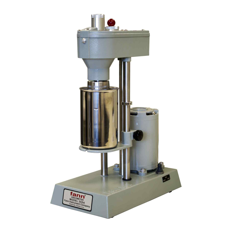
- Page 1 Model 35 Viscometer Instruction Manual Manual No. 208878, Revision N Models 35A, 35SA, 35A/SR-12, and 35SA/SR-12...
- Page 2 Printed in USA. The information contained in this document includes concepts, methods, and apparatus which may be covered by U.S. Patents. Fann Instrument Company reserves the right to make improvements in design, construction, and appearance of our products without prior notice ®...
-
Page 3: Table Of Contents
Features and Specifications ..................9 Installation ......................13 Operation ........................ 14 5.1 Operating the Model 35A and 35SA ............... 15 5.2 Operating the Model 35A/SR-12 and 35SA/SR-12.......... 15 5.3 Measuring Gel Strength .................. 17 5.4 Changing the Rotors, Bobs, and Torsion Springs ........... 18 Instrument Calibration Check .................. - Page 4 Table 3-4 Rotor-Bob Specifications ................12 Table 3-5 Range of Environmental Conditions .............. 12 Table 5-1 Six-Speed Testing Combinations for Models 35A and 35SA ......15 Table 5-2 Twelve-Speed Testing Combinations- Models 35A/SR-12 and 35SA/SR-12 . 16 Table 6-1 Dial Deflection for Calibration Weights and Torsion Spring Assemblies ..25 Table 7-1 Rotor-Bob Factor (C) ..................
-
Page 5: Introduction
The standard power source is 115 volts, but all models may be fitted with a transformer, making operation with 220/230 volts possible. Fann Model 35 viscometers are used in research and production. These viscometers are recommended for evaluating the rheological properties of fluids, Newtonian and non-Newtonian. -
Page 6: Document Conventions
Model 35 Viscometer Instruction Manual Document Conventions The following icons are used as necessary to distinguish elements of text. NOTE. Notes emphasize additional information that may be useful to the reader. CAUTION. Describes a situation or practice that requires operator awareness or action in order to avoid undesirable consequences. -
Page 7: Safety
Safe laboratory practices and procedures should be observed while operating and maintaining the Model 35 viscometer. The safe operation of the Fann Model 35 series viscometer requires that the laboratory technician be familiar with the proper operating procedures and potential hazards associated with the instrument. -
Page 8: Standard B1 Bob
Model 35 Viscometer Instruction Manual Standard B1 Bob The standard B1 bob (furnished with the Model 35 series viscometers) is a hollow bob that must not be used to test samples hotter than 200°F (93°C). Solid bobs are available for testing at higher temperatures. Heated Sample Cup When testing heated samples using the heated sample cups wear the proper hand protection to avoid getting burned. -
Page 9: Features And Specifications
Model 35 Viscometer Instruction Manual Features and Specifications The Fann direct-indicating viscometers are equipped with the standard R1 rotor sleeve, B1 bob, F1 torsion spring, and a stainless steel sample cup. Other rotor-bob combinations and/or torsion springs can be substituted to extend the torque measuring range or increase the sensitivity of the torque measurement. -
Page 10: Figure 3-2 Model 35 Viscometer Schematic
Model 35 Viscometer Instruction Manual Torsion Spring Assembly Gear Shift Knob Lens Gel Knob Dial Pointer Gas Purge Nipple (optional) Coupling Bob Shaft Bearings Splash Guard Stop Scribed Line Motor Speed Bob Shaft Switch 2 Speed Motor Circulating Cup Sample Fill Line (350 ml) Locking Knob Stage... -
Page 11: Table 3-1 Model 35 Viscometer Specifications
35SA/SR-12 207201 39 x 15 x 27 cm 6.8 kg 8 x 16 x 19 in. 26 lb 35A w/ case 101671768 20.3 x 40.6 x 48.3 cm 11.8 kg 8 x 16 x 19 in. 26 lb 35SA w/ case 101671770 20.3 x 40.6 x 48.3 cm... -
Page 12: Table 3-3 Rotor And Bob Dimensions
Model 35 Viscometer Instruction Manual Table 3-3 Rotor and Bob Dimensions Radius Length Unit Cylinder Area (cm ) x Radius (cm) (cm) (cm) 1.7245 71.005 1.2276 35.981 0.86225 17.751 0.86225 8.876 1.8415 1.7589 2.5867 Table 3-4 Rotor-Bob Specifications ROTOR-BOB R1 B1 R2 B1 R3 B1 R1 B2... -
Page 13: Installation
Model 35 Viscometer Instruction Manual Installation The Model 35 should be placed in a position where there is easy access to the power cord plug for disconnection. Consideration should be given to the location where samples are prepared and equipment is cleaned when the test is completed. There should be sufficient storage area nearby for commonly used tools, as well as consumables. -
Page 14: Operation
Model 35 Viscometer Instruction Manual Operation This section describes the operating instructions for the Model 35 series viscometers. It also includes instructions for measuring gel strength and changing rotors, bobs, and torsion springs. To start the test, add 350 ml of pre-stirred sample to the stainless steel sample cup. The sample cup has a line that marks 350 ml as shown in Figure 3-2. -
Page 15: Operating The Model 35A And 35Sa
Model 35 Viscometer Instruction Manual Operating the Model 35A and 35SA The Model 35A and 35SA viscometers operate at six speeds, ranging from 3 rpm to 600 rpm. To select the desired speed, set the speed switch (located on the right side of the base) to the high or low speed position as desired. -
Page 16: Figure 5-1 Gear Box Shift Lever
The shear stress values will appear on the dial. Gear Box Shift Lever Figure 5-1 Gear Box Shift Lever Table 5-2 Twelve-Speed Testing Combinations- Models 35A/SR-12 and 35SA/SR-12 Gear Box Speed Switch Gear Shift... -
Page 17: Measuring Gel Strength
Model 35 Viscometer Instruction Manual Measuring Gel Strength The commonly used procedure for measuring gel strength is as follows: 1. Stir the sample thoroughly at 600 rpm. 2. Set the gear shift knob to the 3 rpm position, and then turn the motor to the OFF position. -
Page 18: Changing The Rotors, Bobs, And Torsion Springs
Model 35 Viscometer Instruction Manual Changing the Rotors, Bobs, and Torsion Springs The R1-B1-F1 rotor-bob-torsion spring combination is standard for all Fann viscometers. Other rotor-bob combinations may be used, provided shear rates are calculated for the fluid being tested. Rotor-bob combinations other than R1-B1 have large gap sizes;... -
Page 19: Figure 5-2 Rotor Removal And Installation
Model 35 Viscometer Instruction Manual 5.4.1 Rotor Removal and Replacement Refer to Figure 5-2. To remove the rotor from its socket, twist the rotor clockwise and gently pull it down. To replace the rotor, align the rotor slot and groove with the lock pin in the main shaft socket. -
Page 20: Figure 5-3 Bob And Bob Shaft
Model 35 Viscometer Instruction Manual 5.4.2 Bob Removal and Replacement The bob shaft end is tapered and fits into a matching tapered hole in the bob. Refer to Figure 5-3. 1. Rotate the rotor clockwise and gently pull it down to remove it. 2. - Page 21 Model 35 Viscometer Instruction Manual 5.4.3 Torsion Spring Removal and Replacement Refer to Figure 5-4. 1. Remove the dust cap [A] and plug screw [B]. 2. Loosen set screws [C] and [D] about one-half turn. The spring can now be lifted out.
-
Page 22: Figure 5-4 Torsion Spring Removal And Replacement
Model 35 Viscometer Instruction Manual Figure 5-4 Torsion Spring Removal and Replacement 208878 Revision N, February 2013... -
Page 23: Instrument Calibration Check
For continuous accurate measurements, the instrument must be properly calibrated. In accordance with API 13B-1 and 13B-2, Fann recommends calibrating the Model 35 before it is placed in service and at least monthly while it is in service. However, calibration frequency depends on your usage and laboratory quality assurance program. -
Page 24: Dead Weight Calibration
Model 35 Viscometer Instruction Manual Dead Weight Calibration This procedure uses the Model DW3 Calibration Kit (P/N 207853). Refer to Figure 6-1. Calibrating Spool Calibrating Fixture Pulley Weight Figure 6-1 DW3 Calibration Fixture 208878 Revision N, February 2013... -
Page 25: Table 6-1 Dial Deflection For Calibration Weights And Torsion Spring Assemblies
Model 35 Viscometer Instruction Manual 1. Remove rotor and bob. Refer to Section 6. Be sure that the tapered end of the bob shaft is clean, and then install the calibrating spool. 2. Install the DW3 calibrating fixture by clamping it onto the upper portion of the viscometer support legs. -
Page 26: Fluid Calibration Check
Fluid Calibration Check This procedure describes the calibration check using only certified Newtonian calibration fluids. Fann calibration fluids are available for separate purchase (Table 9-1). All calibration standards are certified by methods traceable to the United States National Institute of Standards and Technology (NIST). -
Page 27: Torsion Spring Calibration
Model 35 Viscometer Instruction Manual Readings outside the specified limits are indications that the instrument should be either calibrated or repaired. (See Section 6.3 for the procedure to calibrate the spring.) After completion of the calibration check, carefully wipe clean the rotor surfaces (inner and outer), bob, thermometer, sample cup, and work area Torsion Spring Calibration Refer to Figure 5-4 for identification of parts. -
Page 28: Test Analysis
300 rpm and the rotor-bob-torsion spring combination is R1-B1-F1. Other springs may be used provided that the dial reading is multiplied by the "f" factor (spring constant) to calculate the viscosity. To calculate Newtonian viscosities in centipoise with the Fann viscometer, use the following equation: ƞ... -
Page 29: Plastic Viscosity And Yield Point Calculation
Model 35 Viscometer Instruction Manual Table 7-1 Rotor-Bob Factor (C) Table 7-2 Speed Factor (S) Rotor-Bob R-B Factor Rotor Speed Factor Combination (rpm) R1-B1 1.000 333.3 R1-B2 8.915 166.6 R1-B3 25.392 R1-B4 50.787 R2-B1 0.315 R2-B2 8.229 R2-B3 24.707 3.33 R2-B4 49.412 R3-B1... -
Page 30: Spring Constant Calculation
Model 35 Viscometer Instruction Manual Spring Constant Calculation This calculation applies to the dead weight calibration method. × × θ Equation 7-4 where is the spring constant in dyne-cm/degree deflection G is the load in grams g is the gravitational constant at 981cm/sec r is the radius arm at 1cm θ... -
Page 31: Additional Viscosity Calculations
K is the overall instrument constant in (dyne-sec/cm ) (rpm/degree deflection) f is the torsion spring factor θ is the Fann viscometer reading N is the rate of revolution of the outer cylinder η is the viscosity in cP For Equation 7-5, choose the correct K value (overall instrument constant) that matches the rotor-bob combination in Table 7-4. -
Page 32: Table 7-4 Constants For Viscosity Calculations
Oilfield Units (R1-B1-F1) τ • Shear Stress dynes/cm Fann = 5.11 dynes/cm τ • Shear Stress lb/100 ft Fann = 1.065 lb/100 ft Shear Stress τ • lb/100 ft Fann = 1 lb/100 ft (approx.) γ Shear Rate 1/sec 1/sec = 1.7023 N Viscosity µ... -
Page 33: Measuring Ranges
Measuring Ranges The measuring ranges for shear stress, shear rate, and viscosity are listed in Table 7-6, 7-7 and 7-8, respectively. Table 7-6 Shear Stress Measuring Range for Fann Direct Indicating Viscometer θ) Shear Stress Range (dynes/cm ), τ = (k... -
Page 34: Table 7-7 Shear Rate Measuring Range For Fann Direct Indicating Viscometers
Model 35 Viscometer Instruction Manual Table 7-7 Shear Rate Measuring Range for Fann Direct Indicating Viscometers ), γ = k Shear Rate Range (sec Rate of Revolution of Outer Cylinder, N Rotor-Bob Combinations (rpm) R1 B1 R2 B1 R3 B1... -
Page 35: Table 7-8 Viscosity Range In Centipoise For Fann Direct Indicating Viscometers
Model 35 Viscometer Instruction Manual Table 7-8 Viscosity Range in Centipoise for Fann Direct Indicating Viscometers Viscosity (cP) Fann Model Rotor-Bob Combinations R1 B1 R2 B1 R3 B1 R1 B2 R1 B3 R1 B4 All Models, 600 rpm max 12.7 Minimum Viscosity Model 35A &... -
Page 36: Troubleshooting And Maintenance
Replace the bob shaft bearings bearings. (P/N 207450). Bend shaft slightly to Bent bob shaft. straighten it. Contact Fann for Erratic dial motion repair or replacement. Replace the rotor if it is Rotor out of alignment. damaged. See list of rotors in Table 9-1. -
Page 37: Maintenance
Model 35 Viscometer Instruction Manual Maintenance The instrument should be serviced by qualified personnel only. If factory service is required, contact Fann for return authorization. These tips are recommended for properly caring for the viscometer. • Clean the bob and rotor after each test. -
Page 38: Accessories
Model 35 Viscometer Instruction Manual Accessories Table 9-1 Accessories Torsion Springs Part No. Constant Max Shear Stress Color Code 207656 F0.2 77.2 Green 207657 F0.5 Yellow 207465 1,533 Blue 207658 3,066 207659 1,158 4,600 Purple 207660 1,544 6,132 White 207661 1,930 7,665 Black... -
Page 39: Parts List
The Model 35 series of viscometers are listed in Table 10-1. The parts list for the Fann Model 35 viscometers are combined in Table 10-2. See Figure 10-1, the upper half of the Model 35 for identification numbers 1-24 and 43-69 in the parts list. -
Page 40: Figure 10-1 Model 35A And 35Sa - Upper
Model 35 Viscometer Instruction Manual Figure 10-1 Model 35A and 35SA - Upper 208878 Revision N, February 2013... -
Page 41: Figure 10-2 Model 35A And 35Sa - Lower
Model 35 Viscometer Instruction Manual Figure 10-2 Model 35A and 35SA – Lower 208878 Revision N, February 2013... -
Page 42: Table 10-2 Model 35 Series Viscometer Parts List
Drive Shaft Gear (35A) 207563 Drive Shaft Gear (35SA) 205654 O-Ring 207448 Stage 219548 Capacitor. 7.5 µF 207458 Base (Model 35A, 60 Hz) 207204 Base (Model 35SA, 50Hz) 207459 Cover Plate 207500 Name Plate (35A) 207499 Name Plate (35SA) 205779... - Page 43 207587 Idler Shaft 207485 Flat Washer 208365 Switch 207784 Switch Boot 207814 External Retainer 207437 Bearing (2) 207143 Internal Retaining Ring 208003 Idler Gear (35A) 208004 Idler Gear (35SA) 204371 Strain Relief 203512 Power Cord 208878 Revision N, February 2013...
-
Page 44: Warranty And Returns
11.2 Returns For your protection, items being returned must be carefully packed to prevent damage in shipment and insured against possible damage or loss. Fann will not be responsible for damage resulting from careless or insufficient packing. Before returning items for any reason, authorization must be obtained from Fann Instrument Company.
Need help?
Do you have a question about the 35A and is the answer not in the manual?
Questions and answers