
Related Manuals for fann RheoVADR


Summary of Contents for fann RheoVADR
- Page 1 ® RheoVADR Rheometer Instruction Manual Manual No. D00845847, Revision E Instrument No. 102267855 Software Version 1.5 DNA™ System Compatible...
- Page 2 Printed in USA. The information contained in this document includes concepts, methods, and apparatus which may be covered by U.S. Patents. Fann Instrument Company reserves the right to make improvements in design, construction, and appearance of our products without prior notice.
-
Page 3: Table Of Contents
® RheoVADR Rheometer Instruction Manual Table of Contents Introduction ......................6 1.1 Document Conventions ..................7 Safety ........................8 2.1 Safe Electrical Operation .................. 8 2.2 Heated Sample Cup ..................8 Features and Specifications ..................9 3.1 Rheometer Features ..................9 3.2 Rheometer Specifications ................ - Page 4 ® RheoVADR Rheometer Instruction Manual Parts List ........................ 32 Warranty and Returns .................... 36 9.1 Warranty ......................36 9.2 Returns ......................36 Appendix A API Profiles ....................37 Appendix B Viscosity Calculations ................40 D00845847 Revision E, September 2014...
- Page 5 Table 3-3 Range of Environmental Conditions .............. 12 ® Table 5-1 RheoVADR Keypad Functions ..............15 Table 5-2 Viscosity Standards for Springs ..............23 ® Table 7-1 Accessories for RheoVADR Rheometer ............31 ® Table 8-1 RheoVADR Rheometer Models ..............32 ®...
-
Page 6: Introduction
The RheoVADR Variable Automated Digital Rheometer is the latest addition to ® the Fann viscometer family. RheoVADR is a direct-reading instrument for evaluating the rheological properties of fluids, Newtonian and non-Newtonian. The advantages of the this rheometer are its digital display, pre-programmed API tests, data recording feature, and speed range —... -
Page 7: Document Conventions
® RheoVADR Rheometer Instruction Manual Document Conventions The following icons are used as necessary in this instruction manual. NOTE. Notes emphasize additional information that may be useful to the reader. CAUTION. Describes a situation or practice that requires operator awareness or action in order to avoid undesirable consequences. -
Page 8: Safety
® RheoVADR Rheometer Instruction Manual Safety Safe laboratory practices and procedures should be observed while operating and maintaining the rheometer. This section lists some precautions to follow. Safe Electrical Operation This instrument is driven by 100V to 240V, 50/60 Hz electrical power. Heated sample cups and recirculating sample cups (optional) are electrically heated. -
Page 9: Features And Specifications
The DNA System is a proprietary hardware and software system which adds capabilities to existing Fann instruments by connecting them to a computer using Fann’s exclusive Data Acquisition and Control Software. The system combines individual instruments into one integrated system. -
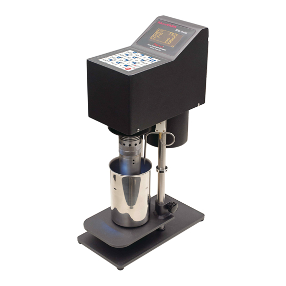
Page 10: Figure 3-1 Rheovadr Rheometer (Front And Back)
® RheoVADR Rheometer Instruction Manual ® Figure 3-1 RheoVADR Rheometer (front and back) D00845847 Revision E, September 2014... -
Page 11: Rheometer Specifications
® RheoVADR Rheometer Instruction Manual Rheometer Specifications ® Table 3-1 RheoVADR Rheometer Specifications Category Specification Torsion Spring F1, F2, F0.2 R1, R2, R3, R1 Closed End, R2 Closed Rotors Bobs B1, B2, B3, B4, B5 Operating Temperature Range 40°F to 125°F (4.44°C to 51.7°C) -
Page 12: Rotor And Bob Specifications
® RheoVADR Rheometer Instruction Manual Rotor and Bob Specifications Table 3-2 Rotor-Bob Specifications and Constants ROTOR-BOB R1 B1 R2 B1 R3 B1 R1 B2 R1 B3 R1 B4 R1B5 Rotor Radius, R (cm) 1.8415 1.7588 2.5866 1.8415 1.8415 1.8415 1.8415... -
Page 13: Installation
® RheoVADR Rheometer Instruction Manual Installation The rheometer should be placed where there is easy access to the power cord plug for disconnection. Consideration should be given to the location where samples are prepared and equipment is cleaned when the test is completed. There should be sufficient storage area nearby for commonly used tools, as well as consumables. -
Page 14: Operation
(1.27cm) or greater. This instrument is operated through a keypad (Figure 5-1). The keypad functions are summarized in Table 5-1 and described fully in the following sections. ® Figure 5-1 RheoVADR Rheometer Keypad D00845847 Revision E, September 2014... -
Page 15: Table 5-1 Rheovadr Keypad Functions
® RheoVADR Rheometer Instruction Manual ® Table 5-1 RheoVADR Keypad Functions Key name Preprogrammed Press white number keys to activate speeds of 1, 2, 3, 6, Speeds 10, 20, 30, 60, 100, 200, 300, or 600 rpm Press to activate blue second function keys Use as Enter key ↵... -
Page 16: Instrument Start-Up
® RheoVADR Rheometer Instruction Manual Instrument Start-up Plug the power supply into a 100V to 240V, 50/60 Hz power source. Connect the power supply to rear of the rheometer. Turn on the power switch. The sample cup will illuminate and the following screens will appear (Figures 5-2 and 5-3). - Page 17 ® RheoVADR Rheometer Instruction Manual The data display (Figure 5-4) lists the temperature ( F), speed (RPM), dial reading (DIAL), and the viscosity in centipoise (cP) in real-time. In the lower right corner of the display, a counter (seconds) shows how long a set speed is running.
-
Page 18: Manual Operating Instructions
• While recording, data is saved in the same file. • To save data in another file (different name), press STOP, and then Record/Pause to record. • To end recording and not file press STOP. File name includes the serial number of the RheoVADR. D00845847 Revision E, September 2014... -
Page 19: Measuring Gel Strength
® RheoVADR Rheometer Instruction Manual 5.2.3 Measuring Gel Strength • Press the STOP button and hold it for 5 seconds. This activates the peak mode (PK) dial reading (shown below). • The instrument displays the peak dial reading for subsequent speed. -
Page 20: Api Test Profile
® RheoVADR Rheometer Instruction Manual API Test Profile Refer to Figure 5-5 and Table 5-1. Figure 5-5 API Test Profiles (pages 1 and 2) This instrument automatically records API test data. Make sure a flash drive (not provided) is connected to the USB port (back of instrument) to save this data. -
Page 21: User Profiles
User 1 and User 2 (Figure 5-5) are custom profiles. See Section 5.4.7 for instructions to load the profiles onto the rheometer. Fann Instrument Company can create User profiles for loading on your instrument using a USB flash drive. Contact Fann Instrument Company for customizing your User profiles. D00845847... -
Page 22: Set-Up Mode
® RheoVADR Rheometer Instruction Manual Set-up Mode This section describes the functions available in SETUP mode (shown below). To enter SETUP mode, press and hold STOP, and then turn on the power. Wait for the SETUP menu to appear. Figure 5-8 SETUP Mode (page 1) -
Page 23: Initiating Temperature Calibration
® RheoVADR Rheometer Instruction Manual 5.4.2 Initiating temperature calibration • Press blue key 2 to select temperature calibration. • Follow temperature calibration steps as shown on screen. • Press STOP to exit and return to previous menu. Use an RTD calibrator (not provided) for calibrating temperature. -
Page 24: Choosing Address
® RheoVADR Rheometer Instruction Manual • Press STOP to exit and return to previous menu. Figure 5-10 Fluid Calibration 5.4.4 Choosing address The device address will be shown (Figure 5-7). Press the blue key 4 to enter the address in the number range 001 to 255. -
Page 25: Choosing Rotor-Bob Combination
® RheoVADR Rheometer Instruction Manual 5.4.5 Choosing Rotor-Bob Combination Press blue keys to select the rotor-bob combination for your instrument. Press fn to see more options (Figure 5-11). Figure 5-11 Rotor-Bob Combinations The selected rotor-bob combination will have an asterisk* next to it. -
Page 26: Applying Firmware Update
® RheoVADR Rheometer Instruction Manual 5.4.6 Applying Firmware Update The update process cannot be interrupted after it begins. Ensure that power is not removed during this process. 1. Insert a USB flash drive in the computer USB Port. Navigate to Windows Explorer and select the Format Command as shown below. - Page 27 3. Download/Unzip the update file “RheoVADR.uc3”. The file name must not be changed. 4. Copy the “RheoVADR.uc3” file to the USB flash drive prepared in Step 2. 5. Safely detach the flash drive from the computer. 6. Turn OFF the rheometer to be updated.
-
Page 28: Installing User Profiles
5.4.7 Installing User Profiles Fann Instrument Company can create User profiles for loading on your instrument using a USB flash drive. Contact Fann Instrument Company for customizing your User profiles. • To load, the custom profile, insert the USB flash drive into rheometer USB port. -
Page 29: Rotor Removal And Installation
® RheoVADR Rheometer Instruction Manual Rotor Removal and Installation • To remove the rotor, turn it clockwise (right). • To install the rotor, turn it counterclockwise (left). Bob Removal and Installation • To remove or install the bob, insert an Allen key wrench (0.050 in.) or similar rod into the hole on the bob shaft as shown in the illustration. -
Page 30: Troubleshooting And Maintenance
® RheoVADR Rheometer Instruction Manual Troubleshooting and Maintenance Contact Fann Instrument Company for repair and maintenance. Make sure the rheometer’s power switch is in the OFF position and unplugged from the source before cleaning, repairing or performing maintenance. D00845847 Revision E, September 2014... -
Page 31: Accessories
102453149 3066 Rotors 102303922 Rotor, R1, RheoVADR Rheometer, Stainless Steel 102372804 Rotor, R1, RheoVADR Rheometer, Closed End, Stainless Steel 102372802 Rotor, R2, RheoVADR Rheometer, Stainless Steel 102372805 Rotor, R2, RheoVADR Rheometer, Closed End, Stainless Steel 102372803 Rotor, R3, RheoVADR Rheometer, Stainless Steel... -
Page 32: Parts List
RheoVADR Rheometer Instruction Manual Parts List ® Table 8-1 RheoVADR Rheometer Models Part No. Description 102406902 RheoVADR Rheometer with F0.2 Spring 102267855 RheoVADR Rheometer with F1 Spring 102453150 RheoVADR Rheometer with F2 Spring ® Table 8-2 RheoVADR Rheometer Parts Item Part No. - Page 33 SCREW, 18-8 SS TRUSS HEAD PHILLIPS 102303923 OVERLAY LCD 102333749 SCREW, TRUSS HEAD PHILLIPS, 18-8 SS 207560 CUP SAMPLE 205778 FEET RUBBER 1/2in. 207487 6-32 X 1/4 BHMS SS 102267850 COVER 102267851 COVER BACK INSTRUCTION MANUAL, RHEOVADR D00845847 RHEOMETER D00845847 Revision E, September 2014...
-
Page 34: Figure 8-1 Rheovadr ® Rheometer Assembly, View 1
® RheoVADR Rheometer Instruction Manual ® Figure 8-1 RheoVADR Rheometer Assembly, View 1 D00845847 Revision E, September 2014... -
Page 35: Figure 8-2 Rheovadr Rheometer Assembly, View 2
® RheoVADR Rheometer Instruction Manual ® Figure 8-2 RheoVADR Rheometer Assembly, View 2 D00845847 Revision E, September 2014... -
Page 36: Warranty And Returns
Fann or, at Fann's option, to the allowance to Customer of credit for the cost of such items. In no event shall Fann be liable for special, incidental, indirect, consequential or punitive damages. -
Page 37: Appendix A Api Profiles
® RheoVADR Rheometer Instruction Manual Appendix A API Profiles Review the following table and notes to better understand the API Profiles. Mode Description Stabilize (S) The unit will run at specified Speed and Run Time, and then check for stability of readings. The dial is considered stabilized if it does not change more than 0.5 dial reading for 10 seconds. -
Page 38: Table A-1 Api Six Speed & Gel Profile
® RheoVADR Rheometer Instruction Manual Refer to the preceding table and notes that explain how data is captured and recorded. Table A-1 API Six Speed & Gel Profile Speed Run Time Number of Points Step Mode (rpm) to Record 0.1 sec interval 10 min 0.1 sec interval... -
Page 39: Table A-3 Api Gel Profile
® RheoVADR Rheometer Instruction Manual Table A-3 API Gel Profile Speed Run Time Number of Points Step Mode (rpm) to Record 0.1 sec interval 10 min 0.1 sec interval Also shows recording rate. For example, Step 3, data points are recorded every 0.1 sec. -
Page 40: Appendix B Viscosity Calculations
® RheoVADR Rheometer Instruction Manual Appendix B Viscosity Calculations To calculate Newtonian viscosities in centipoise, use the following equation: ƞ = S x θ x f x C where, S is the speed factor, = 300 / Test Speed θ is the dial reading... -
Page 41: Table B-2 Torsion Spring Specifications
® RheoVADR Rheometer Instruction Manual Table B-2 Torsion Spring Specifications Torsion Spring Maximum Shear Torsion Constant* Torsion Stress with B1 Color Spring Spring Factor Code Assembly (dyne/cm/degree (dyne/cm deflection) F0.2 77.2 Green F0.5 Yellow 1,533 Blue 3,066 1,158 4,600 Purple... - Page 42 All Rights Reserved. No part of this work covered by the copyright hereon may be reproduced or copied in any form or by any means (graphic, electronic, or mechanical) without first receiving the written permission of Fann Instrument Company, Houston, Texas, USA.
Need help?
Do you have a question about the RheoVADR and is the answer not in the manual?
Questions and answers