
Related Manuals for fann 640


Summary of Contents for fann 640
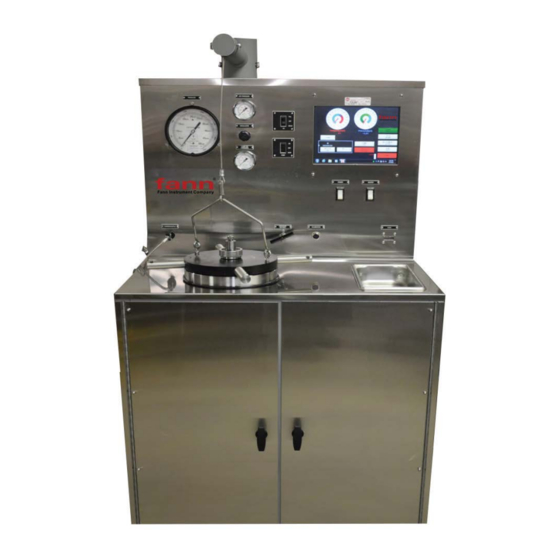
- Page 1 HTHP Consistometer Model 640 & 640CC Instruction Manual Manual No. D01206676 Revision A Instrument No. 102538936 (Model 640) 102546634 (Model 640CC) ©2016 Fann Instrument Company...
- Page 2 Printed in USA. The information contained in this document includes concepts, methods, and apparatus which may be covered by U.S. Patents. Fann Instrument Company reserves the right to make improvements in design, construction, and appearance of our products without prior notice.
-
Page 3: Table Of Contents
Model 640 & 640CC Instruction Manual Table of Contents Introduction ......................6 1.1 Document Conventions ..................7 Safety ........................8 2.1 Safe Pressurization .................... 8 2.2 Safe Heating ...................... 8 2.3 Safe Electrical Operation ..................8 Instrument Overview ....................9 Specifications ...................... - Page 4 Model 640 & 640CC Instruction Manual 11.2 Stopping a Thickening Time Test ..............27 11.3 Calibration ...................... 27 11.4 Pressure Calibration Procedure ..............28 11.5 Consistency Calibration Procedure ..............29 12 Maintenance and Servicing ..................31 12.1 Pressure Valve and Hydraulic System Maintenance ........31 12.2 Potentiometer Mechanism (Pot Mech) Maintenance ........
- Page 5 Model 640 & 640CC Instruction Manual List of Tables Table 4-1 Model 640 & 640 CC Specifications .............. 10 Table 11-1 Consistency as a Function of Weight vs Torque* ........30 Table 13-1 Troubleshooting Model 640 & 640 CC ............40...
-
Page 6: Introduction
The typical test schedules are listed in API Specification 10 on oilwell cements. The Model 640 & 640CC Pressurized Consistometers are able to test cement slurries at temperatures up to 600 F/316 C and pressures as high as 40,000 psig/276 MPa. -
Page 7: Document Conventions
Model 640 & 640CC Instruction Manual Document Conventions The following icons are used as necessary in this instruction manual. NOTE. Notes emphasize additional information that may be useful to the reader. CAUTION. Describes a situation or practice that requires operator awareness or action in order to avoid undesirable consequences. -
Page 8: Safety
Safety Safe laboratory practices and procedures should be observed while operating and maintaining the Model 640 & 640 CC. Follow the instructions provided to avoid personal injuries or damage to the equipment. Always wear appropriate personal protective equipment (PPE) when operating or maintaining the Consistometer. -
Page 9: Instrument Overview
Model 640 & 640CC Instruction Manual Instrument Overview The consistometer Slurry Cup Assembly uses a rotating, cylindrical slurry cup and a stationary paddle assembly enclosed in a pressure vessel. Pressure is applied to the vessel using mineral oil and an air driven hydraulic pump. A tubular heater surrounding the slurry cup supplies heat to the pressure chamber. -
Page 10: Specifications
Model 640 & 640CC Instruction Manual Specifications Table 4-1 Model 640 & 640 CC Specifications Category Specification Electrical 230 VAC (±10%) Input Voltage Input Power 5500W (single), 11000W (dual) Current 24A (single), 48A (dual) Input Frequency 50-60Hz Mechanical Height 70in (175cm) -
Page 11: Installation
Upon uncrating the instrument, verify that the instrument and any spare parts on the packing have been received and are undamaged. Notify Fann if anything is missing or damaged. The instrument’s center of gravity is located near the front of the instrument due to the weight of the pressure vessels. - Page 12 This bracket must be removed prior to using the instrument. On 640 and 640CC consistometers, the counterweight in each swivel arm has been locked in place prior to shipment to prevent the weight from damaging the swivel arm.
- Page 13 Model 640 & 640CC Instruction Manual connectors to maintain consistometer operation during short power outages or interruptions. If an UPS is not used, a jumper cord must be connected between these two connectors or the unit will not power up. An appropriate jumper cord was included with the consistometer accessories.
-
Page 14: Touchscreen Software
Model 640 & 640CC Instruction Manual Touchscreen Software Touch screens were created to provide users with an easy to use interface. This allows the user to input and view data without a keyboard or mouse. The touch surface is able to detect contact and send position information back to the processor. -
Page 15: Instrument Setup
USB memory stick or network location. This function will copy all tests in current C:/FANN data folder and paste them into the selected folder, networked drive, or USB. An AUTO EXPORT function allows the user to select a folder or network storage where any test will be automatically copied to after the test is stopped. -
Page 16: Units
The default location for Fann test files is C:/FANN/Tests. This folder also stores the actual test parameters so any test deleted cannot be run again without reprogramming TEST SETUP. -
Page 17: Test Setup
Model 640 & 640CC Instruction Manual Test Setup From this menu the user can enter or reset a temperature ramp and soak schedule. The user can also configure the hesitation squeeze and gel strength parameters on equipped instruments. This section explains how to use the software to view and print the test results. -
Page 18: Hesitation Squeeze
Model 640 & 640CC Instruction Manual ramp is displayed for confirmation. Press: ACCEPT to save ramp or CANCEL to exit without saving. Hesitation Squeeze On units equipped with the hesitation squeeze option it may be accessed using the button labeled Hesitation Squeeze. Pressing this button will bring up the following screen. -
Page 19: Optional Parameters And Profile Saving
Model 640 & 640CC Instruction Manual Select SAVE to save or Cancel to exit without new schedule. A preview of the schedule will be shown for approval. Optional Parameters and Profile Saving Many optional parameters can be saved in your test profile from the Test Setup screen. -
Page 20: Start Test
Model 640 & 640CC Instruction Manual Start Test Once your instrument is properly configured and a test has been entered in the TEST SETUP section. You may begin testing by selecting the START TEST button from the main menu. Live Testing Screen Once a test has begun, a real-time display of current values will be presented. -
Page 21: Stopping A Test
The default location is C: /FANN/Tests. If auto-shutdown is enabled, the test will be stopped when the Consistency Alarm value has been reached. This action has the same effect as the user pressing the STOP TEST button;... -
Page 22: Front Panel Controls
Model 640 & 640CC Instruction Manual Front Panel Controls All the functions of the consistometer are controlled from the front panel. It is very important for the user to have a thorough understanding of each control and its effect on the operation of the consistometer. -
Page 23: Pneumatic Controls
Model 640 & 640CC Instruction Manual If only one cylinder is to be drained of oil, the AIR EXHAUST must be active. During the draining process the other side of the instrument cannot pump until AIR SUPPLY is turned back on after fully draining the non-active cell. -
Page 24: Cooling Water Controls
The cooling water controls are used to cool the cylinder and oil reservoir at the completion of a test. The Fann pressurized consistometers are optionally equipped with an industry first: internal cooling coils in the oil reservoir for quick cooling of the hydraulic oil and faster turnaround between tests. - Page 25 Model 640 & 640CC Instruction Manual The pump switch may be one of two varieties, depending on whether the automatic pressure control option is installed. If automatic pressure control is not installed, the instrument will be equipped with a switch that is used to turn the pump on and off.
-
Page 26: Operation And Calibration
Model 640 & 640CC Instruction Manual Operation and Calibration 11.1 Running a Thickening Time Test The steps listed below are for experienced users who are familiar with consistometer operation. 1. Close the PRESSURE RELEASE valve if supplied. 2. Turn the POWER switch to the ON position. -
Page 27: Stopping A Thickening Time Test
Model 640 & 640CC Instruction Manual 11.2 Stopping a Thickening Time Test The steps listed below are for experienced users who are familiar with consistometer operation. 1. Stop the test using the touch screen. 2. Turn COOLING ON 3. When temperature has cooled below 212F/100C, open the PRESSURE RELEASE valve and set AIR EXHAUST on DUAL units. -
Page 28: Pressure Calibration Procedure
Model 640 & 640CC Instruction Manual 11.4 Temperature Calibration Procedure Temperature may be calibrated using a temperature calibrator. 1. With Instrument ON and CementLab running, select INSTRUMENT SETUP – CALIBRATE TEMPERATURE. 2. Disconnect thermocouple from inside instrument. The plug is located behind the heater. -
Page 29: Consistency Calibration Procedure
Model 640 & 640CC Instruction Manual FILL the cylinder with oil and then verify pressure gauge readings at different pressures. If optional software pressure display has been purchased pressure unit to maximum typical operating pressure and input the digital calibrator gauge reading into the HIGH VALUE of the software calibration screen. - Page 30 Model 640 & 640CC Instruction Manual 10. Remove some weight and check the CALIBRATED VALUE. If the values are correct, calibration is complete. If the values are incorrect, repeat steps making adjustments to Potentiometer Mechanism as required. Refer to Table 11-1 for weight to Bc conversions for your pot-mech.
-
Page 31: Maintenance And Servicing
Model 640 & 640CC Instruction Manual Maintenance and Servicing Consistometers can be relatively reliable and trouble free - provided they are serviced and maintained properly. Instruments that are neglected and receive infrequent service or are subject to abuse are certain to cause trouble. -
Page 32: Potentiometer Mechanism (Pot Mech) Maintenance
Model 640 & 640CC Instruction Manual The mineral oil supplied with the instrument has an open cup flash point of approximately 188C/370 F. 5. The magnetic drive should be flushed with clean solvent periodically and whenever cement spills into the cylinder or particles contaminate the drive. If cement enters the magnetic drive, it will cause the bearings to wear quickly. -
Page 33: Changing The Metal O-Ring On The Cylinder Assembly
Model 640 & 640CC Instruction Manual pressing the slug out, be careful not to damage the paddle shaft point or the paddle itself. If the slug is not pressed out straight, it may cause the cup sleeve to become oval and prevent the threaded closures from threading into the sleeve. -
Page 34: Replacing The Low Pressure Filter Element
Model 640 & 640CC Instruction Manual 2. Secure the Filter Housing in a vise and remove the Seat Retainer. 3. Compressed air may be forced through the filter element to remove the debris attached to the filter. The filter element may also be unscrewed from the filter nipple and cleaned with solvent or a weak acid solution. -
Page 35: Potentiometer Mechanism Spring Replacement
Model 640 & 640CC Instruction Manual in the mounting frame. The length of resistor extending past the connecting strip should be approximately even on both ends. 4. Seat the resistor securely in the slot in the mounting frame. Use care to avoid damage to the resistor. -
Page 36: Servicing The Inner Magnetic Drive Shaft
Model 640 & 640CC Instruction Manual 12.9 Servicing the Inner Magnetic Drive Shaft It is sometimes necessary to remove the 3-0065 Plug Assembly from the bottom of the 3-0062 Magnetic Drive Housing. The oil in the magnetic drive can create a vacuum that makes removal of the inner shaft difficult, especially if the housing is contaminated. -
Page 37: Removal Of The Magnetic Drive Housing
Model 640 & 640CC Instruction Manual The inner shaft is composed of extremely powerful magnets. If these magnets are allowed to get too close to steel objects the magnetic force may cause injury or damage to the shaft. Also keep the shaft away from metal filings, as they will adhere to the shaft and cause premature wear. -
Page 38: Heater Replacement
Model 640 & 640CC Instruction Manual Use care when working near the heater terminals. They are easily bent or broken. 2. With a spanner wrench, loosen lock ring is found in the recessed hole in the bottom of the pressure vessel. - Page 39 Model 640 & 640CC Instruction Manual 9. Make certain that heater gaskets came out with the heater. If the gaskets did not come out, a 7/16-inch bolt or rod inserted through the bottom of the heater holes will normally snag the gasket and push it out. In lieu of this, a screwdriver may be used to push the gasket out.
-
Page 40: Troubleshooting
Model 640 & 640CC Instruction Manual Troubleshooting The following section consists of a table listing possible remedies for the most common consistometer problems. Table 13-1 Troubleshooting Model 640 & 640 CC Symptom Cause(s) Remedy Check fittings for leaks and tighten fittings. Heater... - Page 41 Model 640 & 640CC Instruction Manual pump muffler, the pump high-pressure seal is probably worn out. Stainless steel lines (3/8 Remove lines and inspect for Pressure cannot be released. inch) are plugged with blockage. Replace any that cement. are plugged.
- Page 42 Model 640 & 640CC Instruction Manual Measure voltage between Check the power supply blue and yellow contact output. If output is pins. If voltage is zero, approximately 15 VDC, use the 15 VDC power and ohm meter to check for...
- Page 43 Model 640 & 640CC Instruction Manual necessary. Faulty heater. Replace. Faulty solid state relay. Replace. Faulty thermocouple. Replace thermocouple. Temperature display is Loose connection in Check for loose wiring and erratic. thermocouple wiring. correct if necessary. Open circuit in Replace thermocouple.
-
Page 44: Warranty And Returns
Fann or, at Fann's option, to the allowance to Customer of credit for the cost of such items. In no event shall Fann be liable for special, incidental, indirect, consequential or punitive damages.
Need help?
Do you have a question about the 640 and is the answer not in the manual?
Questions and answers