Table of Contents
Advertisement
Quick Links
LOVATO ELECTRIC S.P.A.
24020 GORLE (BERGAMO) ITALIA
VIA DON E. MAZZA, 12
TEL. 035 4282111
E-mail: info@LovatoElectric.com
Web: www.LovatoElectric.com
WARNING!
– Carefully read the manual before the installation or use.
– This equipment is to be installed by qualified personnel, complying to current standards, to avoid
damages or safety hazards.
– Before any maintenance operation on the device, remove all the voltages from measuring and supply inpu
and short-circuit the CT input terminals.
– The manufacturer cannot be held responsible for electrical safety in case of improper use of the equipment.
– Products illustrated herein are subject to alteration and changes without prior notice. Technical data and
descriptions in the documentation are accurate, to the best of our knowledge, but no liabilities for errors,
omissions or contingencies arising there from are accepted.
– A circuit breaker must be included in the electrical installation of the building. It must be installed close by
the equipment and within easy reach of the operator. It must be marked as the disconnecting device of the
equipment: IEC /EN/BS 61010-1 § 6.11.3.1.
– Clean the device with a soft dry cloth; do not use abrasives, liquid detergents or solvents.
ATTENTION !
– Lire attentivement le manuel avant toute utilisation et installation.
– Ces appareils doivent être installés par un personnel qualifié, conformément aux normes en vigueur
en matière d'installations, afin d'éviter de causer des dommages à des personnes ou choses.
– Avant toute intervention sur l'instrument, mettre les entrées de mesure et d'alimentation hors tension et
court-circuiter les transformateurs de courant.
– Le constructeur n'assume aucune responsabilité quant à la sécurité électrique en cas d'utilisation impropre
du dispositif.
– Les produits décrits dans ce document sont susceptibles d'évoluer ou de subir des modifications à n'importe
quel moment. Les descriptions et caractéristiques techniques du catalogue ne peuvent donc avoir aucune
valeur contractuelle.
– Un interrupteur ou disjoncteur doit être inclus dans l'installation électrique du bâtiment. Celui-ci doit se
trouver tout près de l'appareil et l'opérateur doit pouvoir y accéder facilement. Il doit être marqué comme le
dispositif d'interruption de l'appareil : IEC/ EN/BS 61010-1 § 6.11.3.1.
– Nettoyer l'appareil avec un chiffon doux, ne pas utiliser de produits abrasifs, détergents liquides ou solvants.
ACHTUNG!
– Dieses Handbuch vor Gebrauch und Installation aufmerksam lesen.
Fachpersonal und unter Befolgung der einschlägigen Vorschriften installiert werden.
Katalog enthaltenen Beschreibungen und Daten sind daher unverbindlich und ohne Gewähr.
/BS 61010-1 § 6.11.3.1.
– Das Gerät mit einem weichen Tuch reinigen, keine Scheuermittel, Flüssigreiniger oder Lösungsmittel verwenden.
ADVERTENCIA
- Leer atentamente el manual antes de instalar y utilizar el regulador.
- Este dispositivo debe ser instalado por personal cualificado conforme a la normativa de instalación
vigente a fin de evitar daños personales o materiales.
- Antes de realizar cualquier operación en el dispositivo, desconectar la corriente de las entradas de aliment
ción y medida, y cortocircuitar los transformadores de corriente.
- El fabricante no se responsabilizará de la seguridad eléctrica en caso de que el dispositivo no se utilice de
forma adecuada.
- Los productos descritos en este documento se pueden actualizar o modificar en cualquier momento. Por
consiguiente, las descripciones y los datos técnicos aquí contenidos no tienen valor contractual.
- La instalación eléctrica del edificio debe disponer de un interruptor o disyuntor. Éste debe encontrarse cerca
del dispositivo, en un lugar al que el usuario pueda acceder con facilidad. Además, debe llevar el mismo
marcado que el interruptor del dispositivo (IEC/ EN /BS 61010-1 § 6.11.3.1).
- Limpiar el dispositivo con un trapo suave; no utilizar productos abrasivos, detergentes líquidos ni disolventes
ni disolventes.
61010-1
§ 6.11.3.1.
AVERTIZARE!
tului.
/BS 61010-1 § 6.11.3.1.
QUICK GUIDE FOR THE CONFIGURATION OF
GB
VARIABLE SPEED DRIVES
VT1...
ATTENZIONE!
– Leggere attentamente il manuale prima dell'utilizzo e l'installazione.
– Questi apparecchi devono essere installati da personale qualificato, nel rispetto delle vigenti
normative impiantistiche, allo scopo di evitare danni a persone o cose.
– Prima di qualsiasi intervento sullo strumento, togliere tensione dagli ingressi di misura e di alimentazione e
cortocircuitare i trasformatori di corrente.
– Il costruttore non si assume responsabilità in merito alla sicurezza elettrica in caso di utilizzo improprio del
dispositivo.
– I prodotti descritti in questo documento sono suscettibili in qualsiasi momento di evoluzioni o di modifiche.
Le descrizioni ed i dati a catalogo non possono pertanto avere alcun valore contrattuale.
– Un interruttore o disgiuntore va compreso nell'impianto elettrico dell'edificio. Esso deve trovarsi in stretta
vicinanza dell'apparecchio ed essere facilmente raggiungibile da parte dell'operatore. Deve essere marchiato
come il dispositivo di interruzione dell'apparecchio: IEC/EN/BS 61010-1 § 6.11.3.1.
– Pulire l'apparecchio con panno morbido, non usare prodotti abrasivi, detergenti liquidi o solventi.
UWAGA!
nikow.
/BS
/BS 61010-1 § 6.11.3.1.
/BS 61010-1 § 6.11.3.1.
/BS 61010-1 § 6.11.3.1.
G
B
1
Advertisement
Table of Contents

Related Manuals for LOVATO ELECTRIC VT1 Series


Summary of Contents for LOVATO ELECTRIC VT1 Series
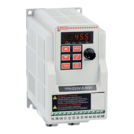
- Page 1 QUICK GUIDE FOR THE CONFIGURATION OF VARIABLE SPEED DRIVES LOVATO ELECTRIC S.P.A. 24020 GORLE (BERGAMO) ITALIA VIA DON E. MAZZA, 12 TEL. 035 4282111 E-mail: info@LovatoElectric.com VT1... Web: www.LovatoElectric.com WARNING! ATTENZIONE! – Carefully read the manual before the installation or use.
-
Page 2: Table Of Contents
STEPS TO FOLLOW FOR THE CONFIGURATION OF THE VARIABLE SPEED DRIVE: LEARN HOW TO RESET HOW DO YOU HOW DO YOU SET THE MOTOR CONFIGURE NAVIGATE THE PARAMETERS TO WANT TO COM- WANT TO PARAMETERS ADDITIONAL MENU DEFAULT MAND THE RUN ADJUST THE FUNCTIONS AND STOP OF... -
Page 3: Navigation In The Menu
1 NAVIGATION IN THE MENU 1.1 OPERATOR PANEL FUNCTIONS TYPE ITEM FUNCTION Digital display and LEDs Main views Frequency, parameters, voltage, current, temperature, fault messages. LED Status – Hz/RPM: ON when the frequency or line speed is displayed. OFF when the parameters are displayed. –... - Page 4 For example, by setting 12-00 = 12345 is enabled the display format shown below. MODE Temperature DC Bus Voltage MODE MODE <4> <3> Feedback PID Output Volage MODE MODE <5> <2> 2SEC. LATER PARAMETER POWER SUPPLY Output Current <1> MODE MODE SET FREQUENCY LED display examples...
-
Page 5: Modifying Parameters
1.3 MODIFYING PARAMETERS To modify the parameters, use the following keys of the frontal keypad: • MODE: it allows to switch from the measures view to the parameter view • : with a quick pressing it is incremented or decremented the selected digit by one (parameter index or value). With an extended pressing it is incremented or decremented the selected digit continuously •... -
Page 6: Command The Run And Stop Of The Motor
3 COMMAND THE RUN AND STOP OF THE MOTOR 3.1 EXTERNAL TERMINAL BLOCK, 2-WIRE MODE, RUN FORWARD / STOP INPUT + RUN REVERSE / STOP INPUT S1 = RUN FORWARD / STOP S2 = RUN REVERSE / STOP RA RB +24V S1 S3 S4 S5 10V ACI AO PARAMETER... -
Page 7: External Terminal Block, 2-Wire Self-Holding Run/Stop
3.4 EXTERNAL TERMINAL BLOCK, 2-WIRE SELF-HOLDING RUN/STOP S1 = RUN FORWARD S2 = RUN REVERSE S3 = STOP RA RB +24V S1 S2 S3 S4 S5 10V ACI AO PARAMETER FUNCTION SETTING DESCRIPTION 00-02 Main run command source selection External run/stop control (terminal block) 00-04 Operation modes for external terminals 2-wire self-holding run/stop... -
Page 8: From Rs485 Communication Port
3.6 FROM RS485 COMMUNICATION PORT RJ45 connector pinout 1: Data+ 2: Data- 3: Data+ 4: Reserved 5: Reserved 6: Data- 7: 5V 8: GND PARAMETER FUNCTION SETTNG DESCRIPTION 00-02 Main run command source selection Communication (RS485) 09-00 Assigned communication station number (serial node) Set the serial node 1…32 09-01 Communication protocol... -
Page 9: From The Potentiometer Integrated On Front
4.2 FROM THE POTENTIOMETER INTEGRATED ON FRONT PARAMETER FUNCTION SETTING DESCRIPTION 00-05 Main frequency source selection Potentiometer on keypad 00-12 Frequency upper limit 50 Hz Insert the maximum frequency limit 00-13 Frequency lower limit 0 Hz Insert the minimum frequency limit 00-14 Acceleration time 10 sec... -
Page 10: From Voltage Analog Input Signal Type 0-10Vdc
4.4 FROM VOLTAGE ANALOG INPUT SIGNAL TYPE 0-10VDC 0 ...10 VDC RA RB +24V S1 S2 S3 S4 S5 10V ACI AO PARAMETER FUNCTION SETTING DESCRIPTION 00-05 Main frequency source selection AVI analog signal input 00-12 Frequency upper limit 50 Hz Insert the maximum frequency limit 00-13 Frequency lower limit... -
Page 11: With Preset Speed Selections
4.6 WITH PRESET SPEED SELECTIONS S1 = RUN / STOP S2 = PRESET SPEED 1 S3 = PRESET SPEED 2 S4 = PRESET SPEED 4 RA RB +24V S1 S5 10V ACI AO Selection table of preset speeds ACTIVATED PRESET SPEED Preset speed 0 (frequency adjusted according to setting of 00-05) Preset speed 1 (05-02) Preset speed 2 (05-03) -
Page 12: From External Up/Down Digital Inputs
4.7 FROM EXTERNAL UP/DOWN DIGITAL INPUTS S1 = RUN / STOP S2 = INCREASE FREQUENCY (UP) S3 = DECREASE FREQUENCY (DOWN) RA RB +24V S1 S4 S5 10V ACI AO PARAMETER FUNCTION SETTING DESCRIPTION 00-05 Main frequency source selection External up/down frequency control 00-12 Frequency upper limit 50 Hz... -
Page 13: Pid Control - Setpoint Adjusted With Keypad And Feedback Signal Type 0/4
4.9 PID CONTROL – SETPOINT ADJUSTED WITH KEYPAD AND FEEDBACK SIGNAL TYPE 0/4…20mA 0/4...20mA RA RB +24V S1 S2 S3 S4 S5 10V ACI AO 2 WIRE SENSOR WITH OUTPUT 0/4-20mA SUPPLIED 24VDC FROM THE DRIVE RA RB +24V S1 S2 S3 S4 S5 10V ACI AO Note. -
Page 14: From Rs485 Communication Port
4.10 FROM RS485 COMMUNICATION PORT RJ45 connector pinout 1:Data+ 2:Data- 3:Data+ 4:Reserved 5:Reserved 6:Data- 7:5V 8:GND PARAMETER FUNCTION SETTING DESCRIPTION 00-05 Main frequency source selection Communication (RS485) 09-00 Assigned communication station number (serial node) Set the serial node 1…32 09-01 Communication protocol Modbus RTU Set the communication speed:... -
Page 15: Motor Parameters
5 MOTOR PARAMETERS PARAMETER FUNCTION SETTING DESCRIPTION 0 = V/f mode 00-00 Control mode 1 = Sensorless vector mode (SLV) Set one of the following Volts/Hz patterns: 1 (50Hz) or 4 (60Hz) = linear (general use) 01-00 V/f characteristic 2 (50Hz) or 5 (60Hz) = linear with high starting torque 3 (50Hz) or 6 (60Hz)= decreasing torque (pumps, fans) 7 = customizable by the user 02-01... -
Page 16: Additional Functions
6 ADDITIONAL FUNCTIONS 6.1 PID CONTROL: FUNCTIONS SLEEP AND WAKE UP For the PID control it is possible to enable the function of sleep and wake up, which allows to decelerate the motor until it stops at the reaching of the PID setpoint value, with consequent energy saving. -
Page 17: Configuration Of The Function Of The Analog Output Ao
The contact type of the relay output RA-RB can be configured with the parameter 03-19: PARAMETER FUNCTION SETTING DESCRIPTION 0 = normally open contact (NO) 03-19 Relay output status type 0 or 1 1 = normally closed contact (NC) 6.3 CONFIGURATION OF THE FUNCTION OF THE ANALOG OUTPUT AO Analog voltage output 0~10VDC To configure the function of the analog output AO (0-10VDC, 1mA max) set the parameter 04-11. -
Page 18: Common Error Codes
7 COMMON ERROR CODES ERROR CODE DESCRIPTION POSSIBLE CAUSES CORRECTIVE ACTIONS – OU – Voltage too high when stopped Detection circuit malfunction Consult with the supplier 1. Power voltage too low 1. Check if the power voltage is correct 2. Pre-charge resistor or fuse burnt out. –... - Page 19 ERROR CODE DESCRIPTION POSSIBLE CAUSES CORRECTIVE ACTIONS The parameter 09-02 is set to 4 but the 1. Use STOP/RESET key of drive to remove the error code OPErr Operator setting error remote keypad (VT1X C02) is 2. Set 09-02 to 0~3 disconnected.
Need help?
Do you have a question about the VT1 Series and is the answer not in the manual?
Questions and answers