Codan 2110 Series Repair Manual
Manpack transceiver
Hide thumbs
Also See for 2110 Series:
- Reference manual (521 pages) ,
- Getting started manual (101 pages) ,
- Getting started manual (90 pages)
Table of Contents
Advertisement
Quick Links
Manpack Transceiver 2110 series
Repair Guide
No part of this guide may be reproduced, transcribed, translated into any language or
transmitted in any form whatsoever without the prior written consent of Codan Limited.
© Copyright 2010 Codan Limited.
CODAN™, NGT™, Easitalk™, CIB™ and CALM™ are registered trademarks of
Codan Limited. Other brand, product and company names mentioned in this document
are trademarks or registered trademarks of their respective holders.
Codan part number 15-04139-EN Issue 1, October 2010.
The English version takes precedence over any translated versions.
Advertisement
Table of Contents

Related Manuals for Codan 2110 Series


Summary of Contents for Codan 2110 Series
- Page 1 Repair Guide No part of this guide may be reproduced, transcribed, translated into any language or transmitted in any form whatsoever without the prior written consent of Codan Limited. © Copyright 2010 Codan Limited. CODAN™, NGT™, Easitalk™, CIB™ and CALM™ are registered trademarks of Codan Limited.
- Page 2 81 Graves Street Newton SA 5074 AUSTRALIA Telephone +61 8 8305 0311 Facsimile +61 8 8305 0411 asiatech.support@codan.com.au Codan (UK) Ltd Unit C4 Endeavour Place Coxbridge Business Park Farnham Surrey GU10 5EH UNITED KINGDOM Telephone +44 1252 717 272 Facsimile +44 1252 717 337 uktech.support@codan.com.au...
-
Page 3: Table Of Contents
Control and switching.............24 Manpack Transceiver 2110 series Repair Guide... - Page 4 Test sheet for the 2110 series Manpack Transceiver........
- Page 5 GPS connector ............. . .131 Manpack Transceiver 2110 series Repair Guide...
- Page 6 Table of contents This page has been left blank intentionally. Manpack Transceiver 2110 series Repair Guide...
- Page 7 The 2110 series Manpack Transceiver ........10...
- Page 8 List of figures This page has been left blank intentionally. Manpack Transceiver 2110 series Repair Guide...
- Page 9 4/5 W output power scale ..........72 Table 18: Typical charging times for Codan battery packs ......86 Table 19: LED indications .
- Page 10 List of tables This page has been left blank intentionally. viii Manpack Transceiver 2110 series Repair Guide...
-
Page 11: Index
PCB 27 battery 18 Antenna Tuner 44 external GPS antenna 13 Audio & Control 40 transceiver unit Front Panel 48 19-way GPIO 14 PA & Filter 37 5-way 15 RF/IF & Synthesiser 33 Manpack Transceiver 2110 series Repair Guide Index-1... - Page 12 AGC 65 options 115 Antenna Tuner 63 ordering information 7 Audio Output 65 output power 130 Basic Receive 63 overview 9 Noise Limiter 67 Selectivity 66 Sensitivity 64 Receive fault diagnosis flowchart 101 Index-2 Manpack Transceiver 2110 series Repair Guide...
- Page 13 60 Handset 62 Power On 59 setting up equipment for 56 receive 63 AGC 65 Antenna Tuner 63 Audio Output 65 Basic Receive 63 Noise Limiter 67 Selectivity 66 Sensitivity 64 Manpack Transceiver 2110 series Repair Guide Index-3...
- Page 14 Index This page has been left blank intentionally. Index-4 Manpack Transceiver 2110 series Repair Guide...
-
Page 15: Introduction
Introduction Overview of this guide This Repair Guide is intended for use by personnel at Codan-trained Service Centres and Accredited Service Centres, enabling rapid and cost-effective servicing of the 2110 series Manpack Transceiver. This guide provides an overview of the equipment and its specifications, functional descriptions, fault diagnosis to board level, board replacement, functional testing and interconnection drawings for the 2110 series Manpack Transceiver. -
Page 16: How To Use This Guide
Introduction How to use this guide The printed version of this guide supplied by Codan contains pages that fold out beyond the folder on either side. This enables you to view block diagrams, test-point layouts and flowcharts while reading relevant text on tests and procedures. -
Page 17: Circuit Board Precautions
Do not use sharp metal tools such as screwdrivers or twist drills to remove CAUTION components as these may damage the printed circuit track and plated thru- holes. A special de-soldering station is recommended for plated thru-holes. Manpack Transceiver 2110 series Repair Guide... -
Page 18: Transmitter Precautions
PA ground plane and the other is earthed to the exciter. This may cause earth loop problems. • Probes should be connected before power has been applied to the transceiver and the test equipment. The earth connection should be made first and disconnected last. Manpack Transceiver 2110 series Repair Guide... -
Page 19: Contact Information
Click on at the top of the page. Outside of normal office hours, Codan has Customer Service Engineers on call to provide emergency technical assistance. They will either answer your call immediately or return your call as soon as possible. - Page 20 Contact information This page has been left blank intentionally. Manpack Transceiver 2110 series Repair Guide...
-
Page 21: Ordering Information
This ensures that the correct items are supplied, and speeds up delivery times. The ordering information for some boards requires an extension to the Codan part number, for example, -101 or -201. Please refer to the listed NOTE spares drawings for this correct extension (see... - Page 22 Ordering information This page has been left blank intentionally. Manpack Transceiver 2110 series Repair Guide...
-
Page 23: Overview
Overview This section contains the following topics: General (10) Connectors (11) Manpack Transceiver 2110 series Repair Guide... -
Page 24: General
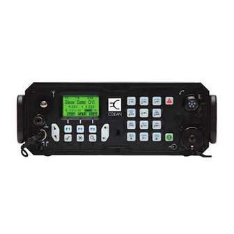
Overview General The 2110 series Manpack Transceiver typically consists of: • a transceiver unit • a battery pack • a handset Figure 1: The 2110 series Manpack Transceiver D I P E I V Manpack Transceiver 2110 series Repair Guide... -
Page 25: Connectors
Options). HF antenna connectors The HF antenna connectors comprise: • an antenna stud ( ) a 50 connector ( ) • The HF antenna connectors are grounded using the earth terminal ( ). Manpack Transceiver 2110 series Repair Guide... -
Page 26: Figure 3: Front View Of The Handset Connector
Pin no. Function Input/output Signal level Ground 10 V p–p maximum (600 ) Earphone Output Input Active low for PTT Microphone (switched) Input 15 mV p–p (ALC threshold) Power Output +12 V nominal Not used Manpack Transceiver 2110 series Repair Guide... - Page 27 Front view of the external GPS antenna connector (2110 only) Table 2: Pinouts of the external GPS antenna connector (2110 only) Connection Function Centre pin Active GPS antenna Sleeve GPS antenna ground For specifications of this connector see Table 25 on page 131. Manpack Transceiver 2110 series Repair Guide...
-
Page 28: Figure 5: Front View Of The 19-Way Gpio Connector (2110 Only)
15.5 V DC approx. 1 A maximum, current limiting Antenna control Input 3.3 V DC logic 5 V DC maximum Input/output 3.3 V DC logic 5 V DC maximum Scan Output Open collector with 1 k pull-down Manpack Transceiver 2110 series Repair Guide... - Page 29 Power in for charging battery Input 15.5 V DC approx. 1 A maximum, current limiting RS232 Tx data Output RS232 (for programming) Morse Input Active low Ground RS232 Rx data Input RS232 (for programming) Manpack Transceiver 2110 series Repair Guide...
-
Page 30: Back Panel
Overview Back panel Figure 7: Back panel of the transceiver unit Manpack Transceiver 2110 series Repair Guide... - Page 31 15.5 V DC @ 1 A maximum, current limiting Battery (+) Input 12 V DC nominal SMB data Input/output 3.3 V DC logic SMB clock Input/output 3.3 V DC logic External PA ALC Input 0 to 5 V DC analogue Manpack Transceiver 2110 series Repair Guide...
-
Page 32: Battery Pack
Charge in Input 15.5 V DC @ 3 A maximum, current limiting Battery (+) Output 12 V DC nominal SMB data Input/output 3.3 V DC logic SMB clock Input/output 3.3 V DC logic Spare Manpack Transceiver 2110 series Repair Guide... - Page 33 Brief description This section contains the following topics: General information (21) Transmit path (22) Receive path (23) Antenna tuning process (24) Synthesiser operation (24) Control and switching (24) Manpack Transceiver 2110 series Repair Guide...
-
Page 34: Brief Description
Brief description This page has been left blank intentionally. Manpack Transceiver 2110 series Repair Guide... - Page 35 Tx AUDIO PIC CLK CODEC Rx AUDIO EARPIECE AUDIO+ AUDIO OUT A/B A/F OUT AUDIO IN + & - AUDIO- GP AUDIO IN + & - GP AUDIO OUT + & - LCD BIAS DISPLAY MUTE DET W/DOG CLKIN CODAN...
-
Page 37: General Information
The transceiver uses double conversion in both the Receive and Transmit modes. The 455 kHz sideband filter, the 45 MHz BPF, the mixers MIX 1 and MIX 2, and the local oscillators VCO and REF OSC, are common to both modes of operation. Manpack Transceiver 2110 series Repair Guide... -
Page 38: Transmit Path
The signal from the PA & Filter PCB is either directly switched to the 50 antenna connector (J2) or switched via a set of impedance-matching components to the antenna stud. Matching components are selected during an iterative tuning process (see page 24, Antenna tuning process). Manpack Transceiver 2110 series Repair Guide... -
Page 39: Rf/If & Synthesiser Pcb
Front Panel PCB. These feed the GPIO external speaker output, the military handset earphone, and the internal speaker. These outputs can be selectively controlled. Manpack Transceiver 2110 series Repair Guide... -
Page 40: Antenna Tuning Process
Filter PCB, RF/IF & Synthesiser PCB, and Antenna Tuner PCB is accomplished via four microcontrollers that share a communications bus. Information exchange between the Audio & Control PCB and Front Panel PCB is accomplished via a separate dedicated data bus. Manpack Transceiver 2110 series Repair Guide... -
Page 41: Interconnection Diagrams And Listed Spares Drawings
Interconnection diagrams and listed spares drawings The drawings in this section are required during repair of a 2110 series Manpack Transceiver. Please refer to the listed spares drawings for ordering information. For example, if you need to order a new Audio & Control PCB 08-06128-001, the listed spares drawing for this indicates that you should order 08-06128-101. - Page 42 Interconnection diagrams and listed spares drawings This page has been left blank intentionally. Manpack Transceiver 2110 series Repair Guide...
-
Page 43: Figure 2: Front Panel Of The Transceiver (2110 Model Shown)
04-03515 CODAN... - Page 44 16-00116 (sheet 1)
-
Page 45: Figure 4: Front View Of The External Gps Antenna Connector (2110 Only)
16-00116 (sheet 2) - Page 46 16-00116 (sheet 3)
-
Page 47: Figure 6: Front View Of The 5-Way Connector (2110V Only)
16-00116 (sheet 4) - Page 48 16-00116 (sheet 5)
-
Page 49: Figure 8: Front View Of The Battery Connector On The Transceiver Unit
16-00116 (sheet 6) - Page 50 16-00116 (sheet 7)
- Page 51 16-00120 (sheet 1)
- Page 52 16-00120 (sheet 2)
- Page 53 16-00120 (sheet 3)
- Page 54 16-00120 (sheet 4)
- Page 55 16-00120 (sheet 5)
- Page 56 16-00120 (sheet 6)
- Page 57 16-00120 (sheet 7)
- Page 59 Audio & Control PCB (40) Antenna Tuner PCB (44) Front Panel Assembly (46) Front Panel PCB (48) The functional description should be read in conjunction with the brief NOTE description (see page 19, Brief description). Manpack Transceiver 2110 series Repair Guide...
- Page 60 Functional description of PCBs This page has been left blank intentionally. Manpack Transceiver 2110 series Repair Guide...
- Page 61 Functional description of PCBs This page has been left blank intentionally. Manpack Transceiver 2110 series Repair Guide...
-
Page 62: Figure 11: Rf/If & Synthesiser Pcb (08-06039-001)
+28 V TP301 Trig. ~5 MHz Tx output VCO volts PLL ref. ref. level adjust align 1 x 0.2 mm TCW KINK DOWN ELEVATION OF FUSE A AND FUSE PA O/P Manpack Transceiver 2110 series Repair Guide... - Page 63 Functional description of PCBs This page has been left blank intentionally. Manpack Transceiver 2110 series Repair Guide...
-
Page 64: Figure 13: Audio & Control Pcb (08-06128-001)
Rx_AUDIO -PAGE1 -PAGE0 DSP_CLK +5VA +9 V AUDIO_IN+ AUDIO_IN- DGND CODEC_CLK 53 54 WDOG_CLKIN Mute adjust R163 Figure 15: Front Panel PCB (08-06129-001) LCD_BIAS DATA+ DATA- SPARE AUDIO- AUDIO+ EARPIECE +1V65 AF_OUT +3V3 +5V_HC Manpack Transceiver 2110 series Repair Guide... - Page 65 VCO • a PIC microcontroller • a Crystal Oven PCB For details on the RF/IF & Synthesiser PCB, See... Codan part number 08-06039-001 Table 8 on page 34 Figure 11 on page 30 Manpack Transceiver 2110 series Repair Guide...
-
Page 66: Table 8: Test Points For The Rf/If & Synthesiser Pcb (08-06039-001)
500 mV p–p Rx with Output Rx audio to Audio & IC206, IC207 –110 dBm (0.7 µV EMF) @ Control PCB 50 port 1 V p–p Rx with –47 dBm (1 mV EMF) @ 50 port Manpack Transceiver 2110 series Repair Guide... - Page 67 0 V DC TP202 440 mV p–p Tx RF side of 455 kHz filter Noise limiter off: 6.3 V p–p Rx @ 455.5 kHz Noise limiter on: 4.8 V p–p Rx @ 455.5 kHz Manpack Transceiver 2110 series Repair Guide...
- Page 68 Tx AF 900 mV p–p Tx Audio input to Tx DEMOD IC302, Audio & Control PCB 200 mV p–p Output of VCO to the PLL V303, VCO 45.25 to 75 MHz in 10 Hz steps Manpack Transceiver 2110 series Repair Guide...
-
Page 69: Pa & Filter Pcb
• an ALC circuit (IC7, IC8)) • thermal control circuit (IC8) For details on the PA & Filter PCB, See... Codan part number 08-06064-001 Table 9 on page 38 Figure 12 on page 30 Manpack Transceiver 2110 series Repair Guide... -
Page 70: Table 9: Test Points For The Pa & Filter Pcb (08-06064-001)
ALC (forward power) – Data (interrupt for PIC) IC104 master PIC, Audio & Control PCB OP ALC Approx. +4.3 V DC Tx OUTPUT 110 V p–p Tx Input/output for Antenna Filter stage Tuner PCB Manpack Transceiver 2110 series Repair Guide... - Page 71 TX_RX 120 mV p–p Tx Input/output for RF/IF & (ensure that the Synthesiser PCB earth lead from the CRO probe is short) +2.2 V DC ALC (output PA collector A rail after F1–F2 voltage) Manpack Transceiver 2110 series Repair Guide...
-
Page 72: Audio & Control Pcb
(IC105, 106, 108) • a battery (G101) • two crystals (Z101, Z201) For details on the Audio & Control PCB, See... Codan part number 08-06128-001 Table 10 on page 41 Figure 13 on page 32 Manpack Transceiver 2110 series Repair Guide... - Page 73 170 mV p–p, single tone Pre-amplified Tx audio from Front Panel PCB the microphone prior to AUDIO_IN+ compression AUDIO_OUT_ Rx audio for the earphone, IC302 internal and external speaker after processing AUDIO_OUT_ +5 V DC IC103 Manpack Transceiver 2110 series Repair Guide...
-
Page 74: Table 10: Test Points For The Audio & Control Pcb (08-06128-001)
Indicates state of 3.3 V and IC106 GOOD 0 V DC, bad 1.8 V regulator R/-W – Data IC301 RESET +3.3 V DC Master reset line IC104 RX_AUDIO 1 V p–p Rx audio RF/IF & Synthesiser PCB Manpack Transceiver 2110 series Repair Guide... - Page 75 Data (serial data for PIC) IC103 – Data IC301 TX_AUDIO 1 V p–p Tx audio Front Panel PCB WDOG_ 3.3 V p–p @ 14 Hz Clock signal from CPLD to IC301 CLKIN CPLD – Not used Manpack Transceiver 2110 series Repair Guide...
-
Page 76: Antenna Tuner Pcb
ALC and therefore maximum output power for taking the measurement. All input signals for measuring Rx voltages are –10 dBm from the RF NOTE signal generator at ±1 kHz from SCF. Manpack Transceiver 2110 series Repair Guide... - Page 77 D24/B detector RESET Reset for all matching relays Synchronous clock for PIC IC104 master PIC, Audio & Control PCB SCLK Synchronous clock for matching Serial data for PIC Set for all matching relays STROBE Manpack Transceiver 2110 series Repair Guide...
-
Page 78: Front Panel Assembly
• 19-way or 5-way GPIO connector depending on variant • 6-way handset connector 50 BNC connector • • antenna stud • GPS antenna, if fitted • external GPS antenna connector, if fitted Manpack Transceiver 2110 series Repair Guide... - Page 79 There are no dedicated test points for this assembly. When ordering a replacement PCB, use the information in the listed spares drawing to select the correct assembly (see page 25, Interconnection diagrams and listed spares drawings). Manpack Transceiver 2110 series Repair Guide...
-
Page 80: Front Panel Pcb
• a connection to the external GPS antenna connector, if fitted • a LED (H1) for backlighting For details on the Front Panel PCB, See... Codan part number 08-06129-001 Table 12 on page 49 Manpack Transceiver 2110 series Repair Guide... - Page 81 Output to earphone on handset IC8 LCD_BIAS Approx. –6 V DC Regulated, temperature- IC16, IC17, IC18 compensated supply for LCD bias +3.3 V DC, unkeyed PTT from handset IC12 0 V DC, keyed SPARE – Not used Manpack Transceiver 2110 series Repair Guide...
- Page 82 Functional description of PCBs This page has been left blank intentionally. Manpack Transceiver 2110 series Repair Guide...
-
Page 83: Repair Procedures, Tests, And Adjustments
Repair procedures and fault diagnosis (55) Disassembling the transceiver (77) Adjustments (79) Re-assembling the transceiver (83) Checking the battery charging process (86) Replacing battery cells (90) Test sheet for the 2110 series Manpack Transceiver (109) Manpack Transceiver 2110 series Repair Guide... -
Page 84: Test Equipment
PC with serial COM port PCMCIA-type is acceptable USB-type is not suitable Codan NSP software 15-04164-EN Programming cable (19-way) For 2110 (08-06237-001) Programming cable (5-way) For 2110v (08-06737-001) DC power cable For 2110 Codan vacuum test jig Manpack Transceiver 2110 series Repair Guide... -
Page 85: Figure 16: Setup For Artificial Antenna
High voltages exist on this artificial antenna when it is in use. Capacitors WARNING must be properly insulated from earth. Figure 17: Setup for RF sampler ´ 3.9 k , 100 V ´ 3.9 k , 100 V Manpack Transceiver 2110 series Repair Guide... -
Page 86: Setup Of Test Equipment For 2110
(optional) Receive audio (front panel) Audio output Power meter (test only) Frequency counter Dummy load 13.6 V power supply WARNING RF signal generator Ensure that polarity of this cable is correct before applying power Manpack Transceiver 2110 series Repair Guide... -
Page 87: Repair Procedures And Fault Diagnosis
Figure 32 on page 101 Receive fault diagnosis flowchart 2 Figure 33 on page 103 Transmit fault diagnosis flowchart 1 Figure 34 on page 105 Transmit fault diagnosis flowchart 2 Figure 35 on page 107 Manpack Transceiver 2110 series Repair Guide... - Page 88 25 W PEP, 2 to 30 MHz Power meter Spectrum analyser Span: 20 kHz Resolution 100 Hz bandwidth: RF signal generator Output: –121 dBm Modulation: 5 V/div 0.1 s/div Connect the transceiver to the test equipment. Manpack Transceiver 2110 series Repair Guide...
-
Page 89: Figure 19: Balance Control On The 0208
Adjust the oscilloscope to view the RF envelope. Adjust the balance control on the 0208 for zero crossover (balanced) on the oscilloscope. Figure 19: Balance control on the 0208 Unbalanced Balanced (zero crossover) Switch off PTT on the 0208. Manpack Transceiver 2110 series Repair Guide... -
Page 90: Mechanical Inspection
• the pins on all connectors are straight and not distorted Record your results and actions (see page 109, Test sheet for the 2110 series Manpack Transceiver). Return to the Repair flowchart (see Figure 29 on page 95). -
Page 91: Operational Tests
Connect the battery. Press on the front panel to switch on the transceiver. Pass Front panel screen displays the Codan logo, then the home screen (typically the channel screen). Hold on the front panel for 2 seconds to switch off the transceiver. -
Page 92: Table 15: Default Settings For The Transceiver During Testing
Control List Cfg Auto Tune Mode Control List ATU/50 Ohm/Codan (antenna selection icon Auto is displayed on screen) Cfg Power Preference Front panel (Tx PWR key) High (Hi is displayed on screen) Control List Manpack Transceiver 2110 series Repair Guide... - Page 93 NOTE using the front panel. Record the name of the test profile that you have programmed into the transceiver (see page 109, Test sheet for the 2110 series Manpack Transceiver). Return to the Repair flowchart (see Figure 29 on page 95).
- Page 94 Hold MUTE to switch on the internal speaker, then listen for noise. Switch off the internal speaker when you have finished testing its NOTE operation. Record your results and actions (see page 109, Test sheet for the 2110 series Manpack Transceiver). Press to exit the Front Panel test.
-
Page 95: Receive Tests
Pass A 1 kHz tone is audible from the 0208, –6 dB at full volume. Record your results and actions (see page 109, Test sheet for the 2110 series Manpack Transceiver). Switch off the RF output from the RF signal generator. - Page 96 Repair procedures, tests, and adjustments Switch the 0208 speaker to Speaker. Return the antenna to the 50 connector ( ). Return the Cfg Auto Tune Mode to ATU/50 Ohm/Codan. Return to the Repair flowchart (see Figure 29 on page 95).
- Page 97 An RF output level from the RF signal generator that is < –106 dBm (RF pre-amp on). Record your results and actions (see page 109, Test sheet for the 2110 series Manpack Transceiver). Switch off the RF output from the RF signal generator.
- Page 98 2110, that is, the audio output from the 2110 should reach approximately 2 V p–p at full volume. Record your results and actions (see page 109, Test sheet for the 2110 series Manpack Transceiver). Switch off the RF output from the RF signal generator.
- Page 99 4.0 kHz below the SCF of the selected LSB channel. Pass A reading on the AC voltmeter that is < 0 dB. Record your results and actions (see page 109, Test sheet for the 2110 series Manpack Transceiver). Switch off the RF output from the RF signal generator.
-
Page 100: Transmit Tests
A reading on the RF power meter that is approximately 5 W PEP. The current drawn on any channel should be < 2 A. Release PTT on the handset. Record your results and actions (see page 109, Test sheet for the 2110 series Manpack Transceiver). Press Tx PWR until Hi is selected. - Page 101 The power to load must be approximately 25 W PEP. Select a channel in the next band, then repeat the test. Record your results and actions (see page 109, Test sheet for the 2110 series Manpack Transceiver). Disconnect the artificial antenna and reconnect the dummy load to the 50 ...
- Page 102 Repair procedures, tests, and adjustments Record your results and actions (see page 109, Test sheet for the 2110 series Manpack Transceiver). Return to the Repair flowchart (see Figure 29 on page 95). Performing the ALC test To test the ALC of the transceiver:...
-
Page 103: Table 16: 20/25 W Output Power Scale
NOTE listed in Table Record your results and actions (see page 109, Test sheet for the 2110 series Manpack Transceiver). For each band, adjust the output level of the 0208 until the RF output power of the transceiver stops increasing, then increase the output level of the 0208 by 10 dB. -
Page 104: Table 17: 4/5 W Output Power Scale
(Bird 43) 36.0 –1.0 Record your results and actions (see page 109, Test sheet for the 2110 series Manpack Transceiver). For each band, adjust the output level of the 0208 until the RF output power of the transceiver stops increasing, then increase the output level of the 0208 by 10 dB. -
Page 105: Figure 20: Acceptable Two-Tone Rf Envelope
The RF waveform envelope is acceptable. If the waveform is acceptable, there is no need to perform the NOTE Intermodulation test. Figure 20: Acceptable two-tone RF envelope Figure 21: Defective two-tone RF envelope (typical overbias of PA) Manpack Transceiver 2110 series Repair Guide... -
Page 106: Figure 22: Defective Two-Tone Rf Envelope (Typical Underbias Of Pa)
Figure 22: Defective two-tone RF envelope (typical underbias of PA) Figure 23: Defective two-tone RF envelope (typical spurious-related problems) Record your results and actions (see page 109, Test sheet for the 2110 series Manpack Transceiver). Switch off PTT on the 0208. -
Page 107: Figure 24: Intermodulation Measurements Using A Spectrum Analyser
Intermodulation products are 26 dB down. Figure 24: Intermodulation measurements using a spectrum analyser IMD measurement (below each tone) Record your results and actions (see page 109, Test sheet for the 2110 series Manpack Transceiver). Manpack Transceiver 2110 series Repair Guide... - Page 108 Analyse the display on the spectrum analyser using Figure Pass Intermodulation products are 26 dB down for each band. Record your results and actions (see page 109, Test sheet for the 2110 series Manpack Transceiver). Switch off PTT on the 0208. Return to the Repair flowchart (see Figure 29 on page 95).
-
Page 109: Disassembling The Transceiver
Locate the open end of the housing over a block of wood that fits within the housing and is approximately 100 mm high, then push the housing down to expose the chassis. Figure 25: Removing the housing from the chassis push housing down evenly over block Manpack Transceiver 2110 series Repair Guide... - Page 110 If the external GPS antenna connector is fitted, disconnect the thick coaxial cable that passes through to the Front Panel Assembly. Do not remove the PCB that covers the keymat from the Front Panel CAUTION Assembly. This can only be re-sealed in the factory. Manpack Transceiver 2110 series Repair Guide...
-
Page 111: Adjustments
These adjustments assume that the transceiver does not have any hardware options. See page 115, Options to identify any hardware NOTE options. You should read the information provided with the options and make adjustments accordingly. Manpack Transceiver 2110 series Repair Guide... - Page 112 DC supply to the output transistors V36 and V37) (see Figure 12 on page 30). Set a multimeter to DC 1 A range and connect it in place of the removed fuse (positive nearest to transistors). Switch on the transceiver. Manpack Transceiver 2110 series Repair Guide...
- Page 113 Check that the two-tone waveform is clean and undistorted. If it is not clean and undistorted, further analysis is required. Switch off PTT on the 0208. Return to the Repair flowchart (see Figure 29 on page 95), if required. Manpack Transceiver 2110 series Repair Guide...
- Page 114 If it is not clean and undistorted, further analysis is required. Switch off PTT on the 0208. Press Tx PWR until Hi is selected. Return to the Repair flowchart (see Figure 29 on page 95), if required. Manpack Transceiver 2110 series Repair Guide...
-
Page 115: Re-Assembling The Transceiver
Tighten the screw that required loosening (labelled). Check the integrity of the sealing gasket, and replace with a new gasket if necessary. Reconnect the battery connector. Push the back panel onto the chassis, then re-insert the six screws. Manpack Transceiver 2110 series Repair Guide... -
Page 116: Figure 26: Setup For Vacuum Test
Wait 5 minutes, then record the reading on the gauge. Pass Final reading is within 3 millibars of the original reading. Unplug the hose from the vacuum adaptor on the back panel. Unscrew the vacuum adaptor. Manpack Transceiver 2110 series Repair Guide... - Page 117 Wait a minute for the transceiver to return to atmospheric pressure. Screw the breather screw back into place, then tighten to 0.7 Nm using a torque screwdriver. Connect the battery pack to the base of the transceiver. Manpack Transceiver 2110 series Repair Guide...
-
Page 118: Checking The Battery Charging Process
• a hand-powered battery charger (1 A at 60 rpm) The Codan 3121 AC Battery Charger and 3122 DC Battery Charger are specially designed for low-noise operation, so receiver performance remains optimal while charging the battery pack via the front panel. -
Page 119: Figure 27: Typical Front Panel Of A Battery Charger
The battery pack has an overtemperature alternating flash condition. Red, double The battery pack has a faulty fuse. flash then long pause Red, rapid flash The battery pack is unserviceable and cannot be charged. Manpack Transceiver 2110 series Repair Guide... - Page 120 • If the battery is detached from the transceiver, use cable 08-06214-001 to connect the output of any of the Codan battery chargers to the 6-way connector on the top of the battery pack. Connect the charger to an appropriate power source.
- Page 121 WARNING damage to the battery. The Codan battery packs have in-built monitoring, which is reported in the Battery entry in the Control List. You should view the Battery Cycle setting for the number of times the battery has received input current (that is, has been charged).
-
Page 122: Replacing Battery Cells
Batteries are considered non-serviceable, and if faulty within the warranty period should be returned via the normal channels to Codan. The instructions below are general. To replace the battery cells: Stand the battery pack on its base. -
Page 123: Replacing The Fuse In The Battery Pack
Remove the 10 screws from the lid of the battery pack. Lift the lid away from the base carefully, taking care with the attached PCB. Remove the fuse from the PCB (see Figure 28 on page 90 for the location of the fuse). Manpack Transceiver 2110 series Repair Guide... - Page 124 Check that the gasket is clean, and sitting correctly within its groove. Gently position the lid onto the battery pack, taking care with the PCB, wiring and the foam lining. Secure the lid in place with the 10 screws. Manpack Transceiver 2110 series Repair Guide...
-
Page 125: Flowcharts
Figure 32 on page 101 Receive fault diagnosis flowchart 2 Figure 33 on page 103 Transmit fault diagnosis flowchart 1 Figure 34 on page 105 Transmit fault diagnosis flowchart 2 Figure 35 on page 107 Manpack Transceiver 2110 series Repair Guide... - Page 126 Repair procedures, tests, and adjustments This page has been left blank intentionally. Manpack Transceiver 2110 series Repair Guide...
-
Page 127: Figure 29: Repair Flowchart
62 page 83 Program transceiver with Audio Output test Frequency test original profile page 65 page 69 Audio & Control PCB Pass test? Pass test? Adjust frequency Test completed suspected faulty page 79 Manpack Transceiver 2110 series Repair Guide... - Page 128 This page has been left blank intentionally. Manpack Transceiver 2110 series Repair Guide...
-
Page 129: Figure 30: Disassembly Flowchart
Replace corroded parts corrosion to internal Check for leaks metal parts? Replace o-rings Are any cables Replace or reconnect damaged or cables disconnected? Tighten fasteners, as any fasteners required loose? Return to Repair flowchart page 95 Manpack Transceiver 2110 series Repair Guide... - Page 130 This page has been left blank intentionally. Manpack Transceiver 2110 series Repair Guide...
-
Page 131: Figure 31: Power On Fault Diagnosis Flowchart
Replace Front Panel Connect P103 on Assembly Audio & Control PCB Is the current Replace RF/IF & drawn > 220 mA, or Synthesiser PCB fuse blows? Return to Repair flowchart page 95 Manpack Transceiver 2110 series Repair Guide... - Page 132 This page has been left blank intentionally. Manpack Transceiver 2110 series Repair Guide...
-
Page 133: Figure 32: Receive Fault Diagnosis Flowchart 1
Check and/or replace coaxial cable RF at J1 between Antenna Tuner 60 mV p–p? PCB and PA & Filter PCB Audio & Control PCB Replace Antenna Tuner or Front Panel PCB suspected faulty Manpack Transceiver 2110 series Repair Guide... - Page 134 This page has been left blank intentionally. Manpack Transceiver 2110 series Repair Guide...
-
Page 135: Figure 33: Receive Fault Diagnosis Flowchart 2
8 and 18 Replace Front Panel PCB 1.2 V p–p? Control PCB and 1.2 V p–p? Front Panel PCB Check and/or replace Handset audio connector on Front Panel Assembly Check internal speaker is switched on Manpack Transceiver 2110 series Repair Guide... - Page 136 This page has been left blank intentionally. Manpack Transceiver 2110 series Repair Guide...
-
Page 137: Figure 34: Transmit Fault Diagnosis Flowchart 1
–10 dBm, J2 between Audio & on pin 2 or 3 then key PTT on 0208 Control PCB and Front of P2? Panel PCB Check TP101 on RF/IF & Synthesiser PCB Manpack Transceiver 2110 series Repair Guide... - Page 138 This page has been left blank intentionally. Manpack Transceiver 2110 series Repair Guide...
-
Page 139: Figure 35: Transmit Fault Diagnosis Flowchart 2
Check RF at centre pin of J1 on Antenna Tuner PCB Check and/or replace coaxial cable RF at J1 between Antenna 60 V p–p? Tuner PCB and PA & Filter PCB Replace Antenna Tuner Manpack Transceiver 2110 series Repair Guide... - Page 140 This page has been left blank intentionally. Manpack Transceiver 2110 series Repair Guide...
-
Page 141: Test Sheet For The 2110 Series Manpack Transceiver
Repair procedures, tests, and adjustments Test sheet for the 2110 series Manpack Transceiver Job details Job number: Date: Technician: Reported fault: Test sheet is used for diagnostic / functional test (circle as required) Transceiver details Unit Serial number Firmware version... - Page 142 < 0 dB ±4 kHz from SCF, RF output level from signal generator –55 dBm, AC voltmeter reading < 0 dB Noise Limiter Faint 1 kHz tone with buzzing is audible from 0208 Manpack Transceiver 2110 series Repair Guide...
- Page 143 Increase in RF output level < 0.5 dB DC supply current @ 3 dB below ALC threshold (with load) DC supply current reduced by 50% @ 3 dB below ALC threshold (without load) Manpack Transceiver 2110 series Repair Guide...
- Page 144 4 to 5 W PEP for each band Band 1 Band 2 Band 3 Band 4 Band 5 Band 6 Band 7 Distortion Oscilloscope: RF waveform envelope is acceptable If Fail, what type? Manpack Transceiver 2110 series Repair Guide...
- Page 145 Band 1 products 26 dB down on each band Band 2 Band 3 Band 4 Band 5 Band 6 Band 7 Spectrum analyser: spurious transmissions and harmonics typically > 60 dB below peak carrier level Manpack Transceiver 2110 series Repair Guide...
- Page 146 Repair procedures, tests, and adjustments This page has been left blank intentionally. Manpack Transceiver 2110 series Repair Guide...
-
Page 147: Figure 36: Gps Receiver
See... GPS Receiver Figure 36 Connector for External GPS Antenna Figure 37 Voice Encryptor Figure 38 Filters Figure 39 Figure 36: GPS receiver FRONT PANEL ASSEMBLY GPS antenna GPS Receiver PCB FRONT PANEL PCB Manpack Transceiver 2110 series Repair Guide... -
Page 148: Figure 37: Connector For External Gps Antenna
Assembly. The GPS connector is optional for 2110 Manpack Transceivers. It is not available for the 2110v. Table 20: Front Panel Assembly and Final Assembly with GPS connector Transceiver Front Panel Assembly Final Assembly 2110 08-06140-003 08-06155-008 08-06155-009 Manpack Transceiver 2110 series Repair Guide... -
Page 149: Figure 38: Voice Encryptor
Options Figure 38: Voice encryptor Encryptor PCB AUDIO & CONTROL PCB Figure 39: Filters Filter assembly RF/IF PCB Manpack Transceiver 2110 series Repair Guide... - Page 150 Options This page has been left blank intentionally. Manpack Transceiver 2110 series Repair Guide...
-
Page 151: Standards And Icons
CAUTION privacy or signal quality NOTE the text provided next to this icon may be of interest to you a step to follow Manpack Transceiver 2110 series Repair Guide... -
Page 152: Definitions
EEPROM electrically erasable programmable read only memory external field-effect transistor forward GPIO general purpose input/output global positioning system high frequency input integrated circuit intermediate frequency Manpack Transceiver 2110 series Repair Guide... - Page 153 REF OSC reference oscillator radio frequency root mean square request to send receive, receiver suppressed carrier frequency serial clock serial data SINAD (signal+noise+distortion)-to-(noise+distortion) ratio system management bus sealed lead acid single sideband tinned copper wire Manpack Transceiver 2110 series Repair Guide...
-
Page 154: Glossary
The unit in a transceiver that modulates audio signals onto radio frequencies that can be transmitted on air, and demodulates the radio frequencies it receives into audio signals. Manpack Transceiver 2110 series Repair Guide... -
Page 155: Circuit Reference Designations
(not including small signal and power diodes) terminals quartz crystal, crystal filter, frequency network Manpack Transceiver 2110 series Repair Guide... -
Page 156: Units
1 mV Power ratio decibel Temperature degrees Celsius °C (degrees Fahrenheit) (°F) Time hour second Voltage volt Unit multipliers Unit Name Multiplier pica 0.000000000001 µ micro 0.000001 milli 0.001 deci kilo 1000 mega 1000000 Manpack Transceiver 2110 series Repair Guide... -
Page 157: About This Issue
About this issue This is the first issue of the Manpack Transceiver 2110 series Repair Guide. Associated documents This guide is one of a series of documents related to the 2110 series Manpack Transceiver. Other associated documents are: • Manpack Transceiver 2110 series Getting Started Guide (Codan part number 15-04136-EN) •... - Page 158 Definitions This page has been left blank intentionally. Manpack Transceiver 2110 series Repair Guide...
-
Page 159: Specifications
Switch off @ 10 V Supply current Transmit: Table 23 on page 130 Receive: no signal 120 mA nominal (standby mode) no signal 145 mA nominal (operating mode) average speech 1 A for battery life calculations Manpack Transceiver 2110 series Repair Guide... - Page 160 3.2 kg (7.1 lb) Sealing IP68 (MIL-STD 810F): immersion for 1 hour at a depth of 1 m (3 ft) Finish colour Dark Grey Microphone Standard military handset with microphone, earphone and PTT push-button switch Manpack Transceiver 2110 series Repair Guide...
-
Page 161: Receiver
+0 [+3] dBm with RF amp on Less than 6 dB variation in output for input variation between 2.0 [1.0] V and 100 mV PD (RF amp on) Fast attack, slow release (selectable release time) Manpack Transceiver 2110 series Repair Guide... -
Page 162: Transmitter
Spurious and harmonic Better than 60 [65] dB below PEP emissions Carrier suppression 50 [60] dB below PEP Unwanted sideband 55 [70] dB below PEP (400 Hz) 65 [70] dB below PEP (1 kHz) Manpack Transceiver 2110 series Repair Guide... -
Page 163: Antenna Tuner
Safe under all load conditions GPS connector Table 25: GPS connector specifications Item Specification DC level 3.3 V ±10% Current limit 150 mA ±50 mA Operating current 5 to 30 mA 10 mA nominal Manpack Transceiver 2110 series Repair Guide... - Page 164 Specifications This page has been left blank intentionally. Manpack Transceiver 2110 series Repair Guide...
Need help?
Do you have a question about the 2110 Series and is the answer not in the manual?
Questions and answers