Table of Contents
Advertisement
Quick Links
Advertisement
Table of Contents

Related Manuals for Shini SAL-700G


Summary of Contents for Shini SAL-700G
- Page 1 SAL-700G "Standard" Separate-vacuum Hopper Loader Date: Aug., 2021 Version: Ver.E...
-
Page 3: Table Of Contents
1.4 Safety Regulations ................10 1.4.1 Safety Signs and Labels .............. 10 Structure Characteristics and Working Principle ........11 2.1 Working Principle .................. 11 2.1.1 SAL-700G Working Principle ............11 2.2 Accessory ..................... 12 2.3 Options ....................12 Installation Layout ..................13 3.1 Installation and Positioning .............. - Page 4 Table 4-2: Symbol status description..............20 Table 4-3:Communication Address(Protocol Modbus-RTU) ...... 21 Picture Index Picture 1-1: "Standard" Separate-vacuum Hopper Loader SAL-700G ....5 Picture 1-2: SMH External Dimension ..............7 Picture 1-3: SVH External Dimension ..............7 Picture 1-4: SHR External Dimension..............8 Picture 1-5: SAL-700G External Dimension ............
-
Page 5: General Description
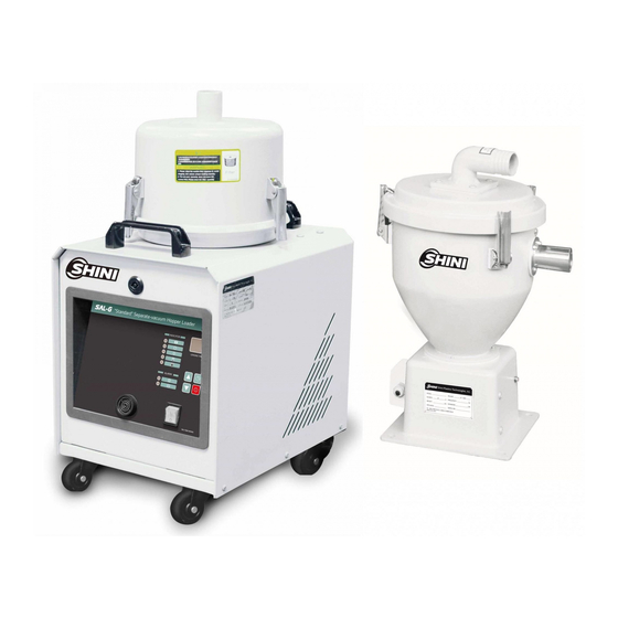
1. General Description Please read through this operation manual before using and installation to avoid damage of the machine and personal injuries. Picture 1-1: "Standard" Separate-vacuum Hopper Loader SAL-700G 1.1 Coding Principle 1.2 Features Microprocessor for ease of use and has multiple alarm indicators. - Page 6 Chapter 6 contains maintenance instructions for service engineers. Other chapters contain instructions for the daily operator. Any modifications of the machine must be approved by SHINI in order to avoid personal injury and damage to machine. We shall not be liable for any damage caused by unauthorized change of the machine.
-
Page 7: Technical Specifications
1.3 Technical Specifications 1.3.1 External Dimension Picture 1-2: SMH External Dimension Table 1-1: SMH Specification Model L(mm) L1(mm) L2(mm) SMH-6L Picture 1-3: SVH External Dimension Table 1-2: SVH Specification Models L(mm) L1(mm) D(mm) R(mm) SVH-6L SVH-12L 7(25) - Page 8 Picture 1-4: SHR External Dimension 8(25)
-
Page 9: Specification
SAL-700G (Main controller) Picture 1-5: SAL-700G External Dimension 1.3.2 Specification Table 1-3: Specification Main Unit Hopper Receiver(s) Motor RS-485 Conveying Suction Conveying Hopper Dimensions Motor Power Dimensions Weight Recommended Weight communication Hose Dia. Pipe Capacity Model Ver. Capacity (mm) function (Inch) Dia. -
Page 10: Loading Capacity
1.3.3 Loading Capacity Horizontal distance ( m) Picture 1-6: Loading Capacity 1.4 Safety Regulations Please abide by the safety guide when you operate the machine so as to prevent damage of the machine and personal injuries. 1.4.1 Safety Signs and Labels All electrical components should be installed by qualified electricians. -
Page 11: Structure Characteristics And Working Principle
2. Structure Characteristics and Working Principle 2.1 Working Principle SAL-700G series are suitable for conveying plastic granules over long distance. Utilizing high efficiency vacuum blower to produce vacuum in material hopper, plastic materials will then be fed into material hopper by air pressure. -
Page 12: Accessory
Turn on the machine, the high pressure blower(1)starts work, it makes storage hopper (4) generate the vacuum. Discharging plate(7) closed, materials in silo get into the storage hopper(3) through material inlet pipe(4) by air pressure. When the loader finishes the work, high pressure blower(1) stop working, materials (5) will drop off due to gravity. -
Page 13: Installation Layout
3. Installation Layout 3.1 Installation and Positioning 1) Machine just can be mounted in vertical position. Make sure there’s no pipe, fixed structure or other objects above the installing location and around the machine which may block machine’s installation, hit objects or injure human person. -
Page 14: Installation Steps Of Matching Hopper
Picture 3-1: Air inlet / outlet 3.4 Installation steps of matching hopper 1) Place the SAL-700G machine at a proper position on the ground. 2) Install the material hopper on the top of the hopper dryer and the sensor hopper onto the plastic injection machine. Connect the signal cord to the machine SAL-700G. -
Page 15: Installation Of Sal-G Optional Cyclone Dust Seperator
Picture 3-3: Use with SMH Picture 3-4: Use with SMH and SCH-U 3.5 Installation of SAL-G Optional Cyclone Dust Seperator 15(25) - Page 16 5) Connect one end of steel wire hose to hopper material inlet, and connect to the suction inlet of storage tank. Rubber tube 2 Rubber tube 2 ACF-1 SAL-700G Rubber tube 1 is connected with cyclone dust collector ACF-1 and SAL-700g,hose 2 is connected to hopper air suction pipe. 16(25)
- Page 17 Picture 3-6: ACF-1 Installation hole position 17(25)
-
Page 18: Operation
4. Operation 4.1 Panel Description Picture 4-1: Panel 18(25) -
Page 19: Parameter Setting
Table 4-1: Panel Description Graphical Name Meaning Explain FULL MAT. It means hopper FULL MAT.LIGHT LIGHT full of materials It means the machine is BLENDING MIXING mixing the materials This alarm SHORTAGE FULL MAT. means the ALARM ALARM machine sucked no materials It means the COMMUNICATIO... - Page 20 Table 4-2: Symbol status description Default Code Status Adjusting Range Value Suction time setting 10 Secs. 1~99 Secs. Necessary spray washing times every 3 Times 1~10 Times several times for operation Necessary cleaing times for reverse 3 Times 1~10 Times running every several times of operation Motor reverse running time 10 Secs.
- Page 21 Table 4-3:Communication Address(Protocol Modbus-RTU) Address (Keep the deposit area) Reading Default Minimum Maximum (decimal Parameters R/Writing Unit Parameters Value Value system) bit 0 shutdown 1 in shudown bit 1 standby 1 in standby bit 2 suction 1 in suction bit 3 Detected shortage 1 in detecting 0x00 time after suction...
- Page 22 0x09 The times of C2 cleaning times 0x0a Suction waiting time Mins. 0x0b 0x02 already running times times 0x0c 0x03 already running times times 1 short of 0x0d bit 0 shortage input signal 0 full mat. materials 0 no bit 1 overload input signal 1 overload overload bit 2, bit3 reserved...
-
Page 23: Troubleshooting
5. Troubleshooting Fault Possible reasons Solutions The main switch and control switch don't Close the main switch and control open or the above two don't connect well. switch and check their connecting. When shortage lasts The microswitch on hopper don't long, and suction Adjust or replace. -
Page 24: Maintenance
6. Maintenance 6.1 Hopper Cleaning(Take SVH as an example) SMH Cleaning: In order to avoid air-blocking and to get smooth conveying. Clean the filter screen inside of material hopper. Unlock the snap hook on the hopper, remove the hopper cover and take out the filter screen, then clean it. Clean the filter periodically or when the suction force is reduced. -
Page 25: Main Body Cleaning
6.2 Main Body Cleaning Filter barrel Filter Filter barrel cover Picture 6-2: Host Unit Cleaning When machine in use, clean the filter periodically or when the suction force is reduced. Take out the filter from the main body, clean the dust accreted on it to ensure good ventilation of the air and to enhance loading capacity.
Need help?
Do you have a question about the SAL-700G and is the answer not in the manual?
Questions and answers