Table of Contents
Advertisement
Advertisement
Table of Contents

Related Manuals for Epson TM200


Summary of Contents for Epson TM200
-
Page 1: Service Manual
TM200 Service Manual Service manual TM200 Rev. No. : V. 1.10... -
Page 2: Table Of Contents
Disassembly, Assembly, and Adjustment ... - 35 - Before Starting disassembly, assembly, and adjustment... - 35 - Using this Manual... - 35 - TM200 Disassembly, Assembly, and Adjustment ... - 36 - Door sensor block Front sensor and paper sensor block... -
Page 3: Features And General Description
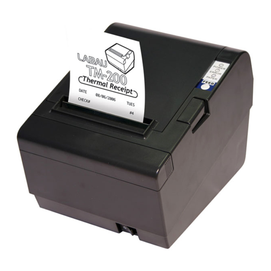
TM200 Service Manual 1 Features and General Description Printer Parts Printer cover Control Panel Cutter cover Cover open button Figure 1-1 TM200 appearance - 1 -... -
Page 4: Printing Specifications
(.035” x .17”) (.07” x .08”) 2.97 x 5.92 5.92 x 2.97 (.11” x .24”) (.24” x .11”) - 2 - TM200 Service Manual Double-weight/ Double-height W x H (mm) 2.47 x5.92 (.10” x .24”) 1.73 x 4.20 (.07” x .17”) 5.92 x 5.92... -
Page 5: Paper Specifications
(3.13" ± 0.02") is 72.2 ± 0.2 mm (2.84" ± 0.008") (576 dots) +24 VDC ± 7% Current consumption (at 24V, normal temperature) Mean: Approximately 1.8A (Font A alphanumeric character printing for all columns) Peak: Approximately 7.8A Mean: Approximately 0.2A - 3 - TM200 Service Manual... -
Page 6: Emi And Safety Standards Applied
15 million lines.) Height: Approximately 138.7 mm (5.46") Width: Approximately 146.5 mm (5.77") Depth: Approximately 195 mm (7.68") Weight: Approximately 1.4 kg (3.08 lb) (except for the paper roll) - 4 - TM200 Service Manual... -
Page 7: Environmental Conditions
Environmental Conditions Temperature: Operating: Storage: Humidity: Operating: Storage: 5 to 45℃ (41 to 113℉) –10 to 50℃ (14 to 122℉) (except for paper) 10 to 90% RH 10 to 90% RH (except for paper) - 5 - TM200 Service Manual... -
Page 8: Major Component Specifications
Type: Cutter motor voltage: Current consumption: Connectors Interface Drawer kick-out Power Supply Connector This connector is used to connect the printer to an external power source. Pin number Signal name +24 VDC Shell Frame GND 4-phase, 48-polarity, PM-type stepping motor 24 VDC ±... -
Page 9: Interfaces
RS-232 serial interface Specifications: Data transmission: Synchronization: Handshaking: Baud rate: Data word length: Parity: Stop bits: Connector (printer side): TM200 Service Manual Direction — Output Input — Output — Output voltage: Approximately 24 V Output current: 1A or less Serial... - Page 10 When the cover is open When an error has occurred When the printer stops printing due to a paper-end(in cases when an empty paper supply is detected by either paper roll end detector or the paper roll near- end detector with a printing halt feature using...
-
Page 11: Buttons, Switches, And Panel Lights
FG –––––––––––––––– FG SG –––––––––––––––– SG Note: Set the handshaking so that the transmitted data can be received. Transmit data to the printer after turning on the power and initializing the printer. Buttons, Switches, and Panel Lights Power Switch Type:... -
Page 12: Dip Switches
POWER: ERROR: PAPER: Note: The panel lights can tell you a lot of information about the situation of the printer, please refer to Appendix C for details. DIP Switches Serial interface model The DIP switches are located at the bottom of the case. - Page 13 Cutter setting Stop bit Cutter mode Reserved: do not change settings Note: TM200 accept ESC/POS command. Dip 1-1 for different printing format, ON(TM200) for 48 characters per line, OFF( Print Density Selection Print Density 1 Low power consumption mode 2 (Normal)
- Page 14 In order to connect Serial port, the host setting should be set as: Data bits Parity check Stop bits Flow control (suggest to set for None) SW 2-7 SW 2-8 OFF(default) OFF(default) Disable Disable 8 bits None 1 bit None - 12 - TM200 Service Manual Enable(default) Enable(default)
- Page 15 Parallel port supports Cutter mode Reserved: do not change settings Note: TM200 accept ESC/POS command. Dip 1-1 for different printing format, ON (TM200) for 48 characters per line, OFF ( Print Density Selection Print Density 1 Low power consumption mode...
-
Page 16: Self-Test
2. Make sure a paper roll has been installed properly. 3. While holding down the FEED button, turn on the printer using the switch on the front of the printer to begin the self test. The self test prints the printer settings, and then prints the following, cuts the paper, and pauses. -
Page 17: Hexadecimal Dump
1B 25 01 1B 63 34 00 1B ←%☺← c 4 41 42 43 44 45 43 47 48 ABCDEFGH 5. Close the cover and turn off the printer or reset it to turn off the hex dump mode. (or to terminate hex dump, press FEED button three times, and when you see the hex dump mode was turned off. -
Page 18: Paper Sensors
After installing new paper roll, close the printer cover; then the printer restarts printing. Cover Open Button When the cover open button (located to the right of the cover) is pressed, the printer cover is opened. When the cover is closed, the cover open button is latched. Note: Be sure to use the cover open button to open the printer cover. -
Page 19: Options
In Southeast Asia: N.A.K. Mfg. (Malaysia) SDN BHD AF50KS-E Jujo Thermal Oy (Finland) P350 (F380), P310 Kanzaki Specialty Papers, Inc. (U.S.A.) PD190R Oji Paper Mfg. Co. Ltd. 90 to 264 VAC 50/60 Hz ± 3 Less than 100 V None None - 17 - TM200 Service Manual... - Page 20 Output specifications Output voltage Rated output current Rated output power Output peak current 24 VDC ± 5% 2.5 A Approximately 60 W 4.5 A (within 300 ms duty 1/6) - 18 - TM200 Service Manual...
-
Page 21: Mechanisms And Operation
Main circuit board unit 2.2 TM200 Printer Mechanism This printer consists of three mechanisms: a printer mechanism and a cutter module. The following illustration shows the external configuration of the TM200. Figure 2.1 TM200 external configuration TM200 Service Manual - 19 -... - Page 22 The paper outlet of the printer is covered, and even if paper output becomes blocked for some reason, there is enough room in the space between the platen and frame cover for accumulation of two or three normal length receipts (the length of one sheet is assumed to be 80mm or less).
-
Page 23: Main Circuit Board Unit
Autocutter Module This printer is equipped with an autocutter module for cutting of the roll paper and a manual cutter for manual cutting. The autocutter has two opposing cutter blades that operate like a scissors to cut the paper. It is a separate cutter blade-type mechanism that does not require passage of the roll paper through an autocutter mechanism slit. - Page 24 TM200 Control Circuit Thermal head driver circuit The print head of the receipt printer mechanism is a thermal type print head with 576 dots per line. All print head control is performed via a gate array. A driver is built into the print head, and sending of print signal DATA-IN, which is synchronized with the CLOCK signal, to the driver sets the print/non-print status of each dot.
-
Page 25: Power Supply Circuit
The cover open sensor is located next to the thermal printer mechanism, and it is connected via Door Sensor board assembly to the main circuit board unit. Detector signal INPUT_4 is input to the CPU. Control Panel Control Circuit This control panel is located on the mainboard. It has three LEDs (POWER, ERROR, PAPER) and one button (FEED). -
Page 26: Switch Circuit Board Assembly
2.4 I/F Circuit Board This printer uses a TM series universal interface, which allows support of a variety of different interfaces by changing the interface board. RS-232 Interface IEEE 1284 Interface USB Interface Multi interface (Parallel and Serial) 2.5 Switch Circuit Board... -
Page 27: Handling, Maintenance, And Repairs
Doing so can cause the cutter blade to be exposed, making it impossible to open the paper roll cover. The heating element of the printer mechanism’s thermal head and the driver IC are easily damaged. Never allow these components to come into contact with metal or other hard objects. -
Page 28: Paper Precautions
Take the paper roll out of the printer when you will not use the printer for a long time in a high temperature and humidity environment. - Page 29 TM200 Service Manual 4. Insert the paper roll as shown. 5. Be sure to note the correct direction that the paper comes off the roll. 6. Pull out a small amount of paper, as shown. Then close the cover - 27 -...
-
Page 30: Problem Solving
1. Turn the printer off and press the cover open button to open the cover. 2. Remove the jammed paper and put the roll back in the printer and close the cover. (Take care not to touch the print head.) 3. -
Page 31: Clearing Paper Jams
4. Correct the problem that caused the paper jam and reload the paper roll into the unit. Note: See the section “Loading paper roll” for details on how to load paper roll. TM200 Service Manual - 29 -... -
Page 32: Inspection And Maintenance
Note that the thermal head (thermal element and radiation plate) becomes very hot during normal operation, creating the danger of burn injury. Be sure to wait for about 10 minutes after turning printer power off before beginning the cleaning. TM200 Service Manual... - Page 33 Such agents can cause deformation, deterioration, and damage to plastic and rubber components. Dirt, lint, dust Use a vacuum cleaner to completely remove all dirt, lint, and dust. Radiation plate Head Thermal element - 31 - TM200 Service Manual...
-
Page 34: Troubleshooting
2. Check the main circuit board unit. 3. Unplug the printer. Then unplug each motor or coil's connector from the main board one by one; plug the printer back in, and power it on. This will let you know if any motor or coil has burned out and is pulling down the power. -
Page 35: Error Types And Processing
The printer executes the following operations upon detecting an error. Stops all printer operations. Flashes the ERROR LED. Data Receive Error (only with the serial interface model) If one of the following errors occurs during serial interface communications, the printer ignores the data Parity error Framing error Overrun error... - Page 36 The following shows the locations of the main elements on the main circuit board unit. CPU (U1) Autocutter drive (J5~J8) Thermal Head power MOS (Q14, Q15) - 34 - TM200 Service Manual ROM (U10, Low byte) ROM (U12, High byte) Paper feed motor driver (U31)
-
Page 37: Disassembly, Assembly, And Adjustment
Not all of the parts (service parts) are indicated as titles. Disassembly, Assembly, and Adjustment Procedures The procedures in this manual are arranged so the entire printer is disassembled when performed from beginning to end. Disassembly of some parts and blocks may be impossible unless performed in accordance with the procedures described in this manual. -
Page 38: Tm200 Disassembly, Assembly, And Adjustment
5.3 TM200 Disassembly, Assembly, and Adjustment There are 5 block of TM200 showing as following, Door sensor block Paper out sensor block and paper sensor block Autocutter module Thermal head module Main circuit board Please following the steps for disassembly,... - Page 39 1. Loose 4 screws beside the thermal cover and move them. 2. Screwing 4 screws (the place indicated by the red circle on the photo) on the bottom of the unit. 3. Reverse the printer, move the body cover apart. Note: You may use your thumb push down the lever while the other fingers forcing up the body cover.
- Page 40 TM200 Service Manual 4. Open the up cover. 5. Move the 2 screws are circled indicated on the photo. To install, reverse the removal procedures. - 38 -...
- Page 41 1. Loose 4 screws beside the thermal cover and move them. 2. Screwing 4 screws (the place indicated by the red circle on the photo) on the bottom of the unit. 3. Reverse the printer, take the body cover apart. Note: You may use your thumb push down the lever while the other fingers forcing up the body cover.
- Page 42 4. Remove the screws on the bottom of the printer mechanism . 5. Remove 2 screws circled on the photo and all the connections between printer mechanism and main circuit board. Then, you can depart printer mechanism from its main board.
- Page 43 TM200 Service Manual 6. Paper sensor connecter beside the printer mechanism as the photo. 7. Remove the screw on the bottom of the printer mechanism as circled on photo, the paper out sensor could be moved then. To install, reverse the removal procedure.
- Page 44 1. Loose 4 screws beside the thermal cover and move them. 2. Screwing 4 screws (the place indicated by the red circle on the photo) on the bottom of the unit. 3. Reverse the printer, take the body cover apart. Note: You may use your thumb push down the lever while the other fingers forcing up the body cover.
- Page 45 TM200 Service Manual 4. Remove the 2 screws beside the autocutter and the connections from circuit board. To install, reverse the removal procedure. CAUTION : When you installed the autocutter module, you must follow the steps below. If you do not follow them, it could cause an autocutter operation failure.
- Page 46 1. Loose 4 screws beside the thermal cover and move them. 2. Screwing 4 screws (the place indicated by the red circle on the photo) on the bottom of the unit. 3. Reverse the printer, take the body cover apart. Note: You may use your thumb push down the lever while the other fingers forcing up the body cover.
- Page 47 TM200 Service Manual 4. Remove the 2 screws beside the autocutter and the connections from circuit board. 5. Stretch your forefinger to the bottom of the thermal head module and force up to depart it from the printer mechanism. 6. Remove the connections from circuit board.
- Page 48 CAUTION: Note that the (thermal head) becomes very hot during normal operation, creating the danger of burn injury. Be sure to wait for about 10 minutes after turning printer power off before beginning the procedures. When performing procedures, be sure to use a grounded wrist band or take other measures to protect against electrostatic charge.
- Page 49 1. Loose 4 screws beside the thermal cover and move them. 2. Screwing 4 screws (the place indicated by the red circle on the photo) on the bottom of the unit. 3. Reverse the printer, take the body cover apart. Note: You may use your thumb push down the lever while the other fingers forcing up the body cover.
- Page 50 4. Remove the screws on the bottom of the printer mechanism . 5. Remove 2 screws circled on the photo and all the connections between printer mechanism and main circuit board. Then, you can depart printer mechanism from its main board.
- Page 51 There are 2 ROMs on the board, the one is LOW bye(U10), the other one is HIGH byte(U12), please make sure the ROM be placed to the correct place. After removing these circuit boards, be sure to protect them against electrostatic charge damage by placing them in an anti-static bag. - 49 - TM200 Service Manual...
-
Page 52: Appendix A Interface
The printer is not equipped with any online/offline switch. The printer is placed into offline status in either of the followings: 1. When the power is turned on or until the printer becomes ready for data transmission after it is initialized by the reset signal from the interface. -
Page 53: Interface Pin Assignments
Strobe received, Waiting on Acknowledge Paper Out / Paper Error Daisy-Chain Device Select Signal Auto-Feed paper Cancel Current Job (May be called /PRIME) Select In; Taking low or high sets printer on line or off line - 51 - TM200 Service Manual... -
Page 54: Appendix B Exploded Diagram
TM200 Service Manual Appendix B Exploded diagram... -
Page 55: Appendix C Panel Lights And Indicators
Power - Green Error - Red blinking Paper - Red and Green blinking Power - Green Error - Red Paper - Green Power - Green Error - Red blinking Paper - Green - 53 - TM200 Service Manual Panel status... - Page 56 Power - Green Error - Red Paper - OFF Power - Green Error - Red Paper - Red Power - Green light blinking Error - Red light blinking Paper - Red light blinking - 54 - TM200 Service Manual Panel status...
-
Page 57: Appendix D Parts Number List
Parallel printer cable, white color, 36 pin Parallel printer cable, black color, 36 pin Serial (RS232 32K buffer) port interface board Serial printer cable, white color, 9 to 25 pin Serial printer cable, black color, 9 to 25 pin USB port interface board...
Need help?
Do you have a question about the TM200 and is the answer not in the manual?
Questions and answers