Advertisement
Thanks to an internal oscillator, the L-5 module will consecutively connect each output, disconnecting the previous one. Once
reached the last one, the circuit will automatically restart the sequence from the first. The obtained effect will be identical than
the lights present in roads.
The operating speed adjustment between outputs is done through a potentiometer inserted in the circuit.
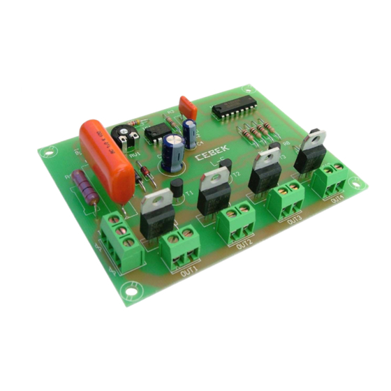
It includes output for external potentiometer and connection terminals to make easier the assembly.
POWER SUPPLY. The module L-5 had to be supplied by 230 VAC. Directly from the mains. See General Wiring map. Using an
adequate plug and a cable for mains connect this last one to the input terminal 230 VAC. Install a fuse and a switch as it is
indicated in General Wiring Map. Both are necessary to protect the module and for your own security, as it is indicated in EEC
regulations. Then, verify that you have correctly connected the module.
Do not forget that in several part of the module there is voltage (230 VAC), for this reason we suggest you to be careful.
OUTPUT CONNECTION. LOAD. The module only accepts resistive loads like lamps, resistors, heatsinks, etc...Do never
connect to the output inductive loads like transformers, fluorescent or halogen lamps with transformers, etc... The minimum
load for each output is 50 W., if you connect an inferior load the module doesn't properly work. In he same case, the maximum
load per output is 250 W., do never overpass this quantity to avoid damaging the module.
To connect outputs, you have to connect bulbs or load to the terminals indicated on the "General Wiring Map". As the module is
operating with a Triac, this one can produce some electrical parasites (noises) or interferences on other apparatus. To avoid this
possibility, you have to install in each output a mains filter as it is indicated in the drawing : "How to install a mains Filter".
OPERATING MODE. Once power supply and outputs installations done, the module is ready to be used, activating the switch to
supply the module. Outputs will be automatically connected one by one, disconnecting the previous one. To adjust the jump
speed between two outputs, you have to adjust the RV1 potentiometer. If you wish to increase the maximum connection time
per output (form factory it is 4 sec), you have to substitute the supplied RV1 potentiometer by a potentiometer with higher value.
The L-5 module offers the possibility to connect an external potentiometer to optimize the assembly. If you want to substitute it,
you have to remove the RV1 potentiometer from the circuit. Then, connect the external potentiometer to the piece terminals or
JP1 jumper. The cable length for this installation must to be inferior to 25cm and the installed potentiometer must to have the
same value that the substituted one, otherwise the timing will change.
INSTALLATION. Do not install the L-5 under bad weather, even if it is protected against meteorological conditions. You have to
install it into a plastic box.
During its operating, the module dissipates heat, for this reason, the used box must to be well ventilated.
Voltage............................................................230 V.AC.
Minimum Consumption....................................100mA.
Maximum Consumption...................................According load.
Minimum power per load............................50W
Maximum power per load...........................250W
Minimum connection time per load...............0,1 sec
Maximum connection time per load..............4 sec
Dimensions. ...................................................102x76x25 mm.
www.cebek.com
www.cebek.com
-
-
sat@cebek.com
sat@cebek.com
4 TRIAC OUTPUTS
SECUENCIAL
L-5
TEHNICAL CHARACTERISTICS
Advertisement
Table of Contents

Related Manuals for CEBEK L-5


Summary of Contents for CEBEK L-5
- Page 1 It includes output for external potentiometer and connection terminals to make easier the assembly. POWER SUPPLY. The module L-5 had to be supplied by 230 VAC. Directly from the mains. See General Wiring map. Using an adequate plug and a cable for mains connect this last one to the input terminal 230 VAC. Install a fuse and a switch as it is indicated in General Wiring Map.
- Page 2 GENERAL WIRING MAP www.cebek.com sat@cebek.com...
Need help?
Do you have a question about the L-5 and is the answer not in the manual?
Questions and answers