Advertisement
E L E C T R O N I C C I R C U I T S
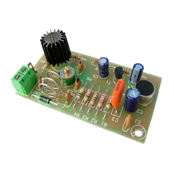
MINI-EMITTER F.M
The FM-1 module is an mini-emitter, specially designed to start in the Radio amateur field. You could emit in
the commercial band from 88 up to 108 MHz. and receive through any radio with F.M band. It includes
microphone.
The module is supplied from 9 up to 15 VDC. We recommend you our FE-2 power supply or a 12 VDC
TECHNICAL CHARACTERISITCS.
Voltage............................................................................................
Consumption..................................................................................
Operating Frequency.......................................................................
Protection Against Polarity Inversions..............................................
Sizes.................................................................................................
OPERATING.
POWER SUPPLY OF THE MODULE. The FM-1 circuit have to be supplied by a 12 VDC power supply correctly
filtered. Do not use suppliers or rectifiers disturbing the module's operating. Then, we recommended you the
FE-2 power supply which has been developed to perfectly answer to the circuit needs or a 12 VDC Battery for
mobile applications.
Install a fuse and a switch as it is indicated in the drawing. Both are necessary and obligatory to assure a
correct module's protection as well as for your own safety as it is indicated in the "CE" regulation.
Connect the positive and the negative of the power supply to the corresponding input indicated in the wiring
map. Use cable as short as possible. Verify that assembly has been correctly done.
ANTENNA CONNECTION. As antenna for our FM-1 module, you could use any metallic rod with a length of 72
cm. The distance between module and antenna had to be as short as possible and try to install antenna
directly to the module output. If you have to use cable for this connection, the cable had to be shielded and
inferior than 20 cm. Do not connect module to the power supply if the antenna is not connected to avoid
to damage output transistors.
The positive cable of the antenna does not touch the enclosure where the module will be installed.
INSTALATION. To obtain a correct operating of the module, it has to be installed in a metallic box and the
ground has to be connected.
OPERATING. To adjust the emitter, use a commercial radio with FM. Place it at 3 m away from the FM-1 module
and adjust the reception between 100 and 104 Mhz.
Verify that the antenna is connected to the module and then supply the module. Using a plastic screw- driver
adjust the emission frequency thanks to the trimer. When you listen to a noise from the receiver you have to
adjust the receiver frequency up to obtain the sound emitted thanks the microphone.
12 VDC. (from 9 to 15)
50 mA.
From 85 to 110 Mhz.
Yes.
69 x 39 x 20 mm.
1
FM-1
FM-1
Advertisement
Table of Contents

Related Manuals for CEBEK FM-1


Summary of Contents for CEBEK FM-1
- Page 1 INSTALATION. To obtain a correct operating of the module, it has to be installed in a metallic box and the ground has to be connected. OPERATING. To adjust the emitter, use a commercial radio with FM. Place it at 3 m away from the FM-1 module and adjust the reception between 100 and 104 Mhz.
- Page 2 If you have any doubt, you could contact your wholesaler or our Technical Department. - E-Mail, sat@cebek.com | Fax. 34.93.432.29.95 | by mail. P .O. Box. 23455 - 08080 Barcelona - Spain. - Keep the invoice of this module. For any repair, the corresponding invoice had to be added. If the invoice is not presented together wish this module, the module’s warranty will be automatically cancelled.
Need help?
Do you have a question about the FM-1 and is the answer not in the manual?
Questions and answers