Table of Contents
Advertisement
Quick Links
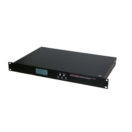
10 Channel GNSS Locked, Low Noise, Rubidium Frequency
Reference with RS232, Display and optional Ethernet-SNMP
All information provided herein is the proprietary property of Novus Power Products
LLC. The information included may be reproduced without the permission or prior
approval of Novus Power Products LLC for the purpose of operating the equipment.
Page #:
1
USERS GUIDE
REVISION
DATE
NR2310D-ROG
www.novuspower.com
NR2310D-ROG
N
031121
Advertisement
Chapters
Table of Contents

Related Manuals for Novus NR2310D-ROG


Summary of Contents for Novus NR2310D-ROG
- Page 1 All information provided herein is the proprietary property of Novus Power Products LLC. The information included may be reproduced without the permission or prior approval of Novus Power Products LLC for the purpose of operating the equipment. Page #: www.novuspower.com...
-
Page 2: Table Of Contents
USERS GUIDE NR2310D-ROG REVISION DATE 031121 Contents Contents ........................2 Safety .......................... 4 Mounting ........................5 Summary........................6 The GNSS-Locked Reference ..................7 The Time Base ......................8 The GNSS Receiver ....................9 Stability Selection Types ..................12 Dual-Time Base Frequency Verification (option) ..........19 External PPS Locking ................... - Page 3 Channel 1 through 10 output connectors – BNC or SMA ........39 PPS – SMA (with GPS locking option) ..............39 Alert – BNC-SMA ....................39 Power In ........................ 39 Functional Description (Base NR2310D-ROG) ............40 Outputs ......................... 40 Built-in Test ......................40 Power Supplies ...................... 41 Redundant power ....................
-
Page 4: Safety
USERS GUIDE NR2310D-ROG REVISION DATE 031121 Safety This product has been designed and manufactured to recognized safety standards and rules. The product is a sophisticated electronic instrument that should be installed and operated by highly trained professionals. Installation of this equipment should comply with all local electrical codes. -
Page 5: Mounting
For applications where there is significant shock and vibration, Novus offers equipment with interior mechanical design features to minimize the effects of vibration and shock on the equipment performance. -
Page 6: Summary
DATE 031121 Summary The NR2310D-ROG is a high performance 10 channel, 10 MHz, GNSS Locked Rubidium frequency reference. The core time base is a Rubidium source that is disciplined with the timing information from the GNSS. The Rubidium source is followed by a low noise OCXO locked to the Rubidium. -
Page 7: The Gnss-Locked Reference
OCXO, a Rubidium or some other device - is controlled. Environmental factors such as temperature, shock and vibration all impact the overall system. Over the years, Novus has invested heavily in the design of locked references and can offer four levels of GNSS locking performance. Each level of performance is discussed to allow the system designer to determine the level of performance required versus system cost constraints. -
Page 8: The Time Base
031121 The Time Base The heart of the system is the reference. Novus offers OCXO and Rubidium based references. Because of the relatively poor phase noise performance of Rubidium, many of our customers select a Rubidium with a cleanup OCXO to achieve high stability and low phase noise. -
Page 9: The Gnss Receiver
There are likely hundreds of GNSS receivers available with a range of functionality. Novus uses a few that are selected to meet the needs of our reference and PPS (pulse per second) sources. PPS stability and accuracy varies with each radio and cost rises with performance. - Page 10 USERS GUIDE NR2310D-ROG REVISION DATE 031121 Depending upon the locking algorithm, the radio PPS variation can contribute directly to phase noise and uncertainty. Novus uses two types GNSS receivers depending upon the stability options installed in the unit. Page #: www.novuspower.com...
- Page 11 USERS GUIDE NR2310D-ROG REVISION DATE 031121 RADIO RECEIVER COMPARISON Standard Advanced Channels Supported Channels L1C/A (1575.42 Mhz) L2C(1227.60 MHz) GLONASS L1OF(1602MHz) L20F(1246 MHz) Galileo E1-B/C(1575.42) E5-b(1207.140MHz) BeiDou B1l(1561.098MHz) B2l(1207.140Mhz) Sensitvity Tracking -161 -167 Hot Start -161 -157 Cold Start -147...
-
Page 12: Stability Selection Types
USERS GUIDE NR2310D-ROG REVISION DATE 031121 Stability Selection Types Standard GNSS-Locked Reference – Analog Loop In the case of a basic reference, which is acceptable for many applications, the OCXO is controlled using a loop as indicated below: The standard loop does an outstanding job of controlling an OCXO. - Page 13 USERS GUIDE NR2310D-ROG REVISION DATE 031121 Basic Digital Locking Loop (HS1) Though the analog loop is acceptable for many applications, the devices within the loop present barriers that are difficult to overcome. Achieving very long time constants requires larger and larger capacitors which present leakage current issues.
- Page 14 USERS GUIDE NR2310D-ROG REVISION DATE 031121 The HS1 improves Allan Deviation by an order of magnitude and close-in phase noise by 10 dB. Page #: www.novuspower.com...
- Page 15 USERS GUIDE NR2310D-ROG REVISION DATE 031121 Page #: www.novuspower.com...
- Page 16 USERS GUIDE NR2310D-ROG REVISION DATE 031121 Advanced GNSS-Locked Reference (HS2) Our most advanced designs address long time constants digitally. High performance picosecond measurement techniques provide greater timing resolution. Advanced algorithms coupled with precise analog designs that are thermally controlled, and vibration isolated allow Allan Deviation performance approaching E-14.
- Page 17 USERS GUIDE NR2310D-ROG REVISION DATE 031121 Our algorithms process the radio information to achieve a more stable reference. The curve below is a plot of timing jitter after processing: The standard deviation improved from 17 ns to approximately 400 picoseconds. The most advanced loop reports calculated Allan Deviation on real time basis locally on a display and/or a selected comm port.
- Page 18 Thermally Isolated Reference (HS3) Thermally and Vibration Isolated Reference (HS4) To further enhance performance Novus offers thermal and vibration isolation. The thermally isolated unit adds a thermal plate held at a fixed temperature and an additional case around the reference to provide insulation. The vibration option adds vibration isolators to attenuate shock and vibration coming from the environment.
-
Page 19: Dual-Time Base Frequency Verification (Option)
USERS GUIDE NR2310D-ROG REVISION DATE 031121 Dual-Time Base Frequency Verification (option) GNSS locked references find application in laboratories where the integrity of the source must be beyond question. With a GNSS locked source, there could be a source malfunction that could cause the source to be in error. To be able... -
Page 20: External Pps Locking
USERS GUIDE NR2310D-ROG REVISION DATE 031121 External PPS Locking The unit may be configured to lock to an external PPS signal. The signal must conform to 3.3 V CMOS into a 1000 Ohm load. Rise time must be less than 10ns and the pulse width must be greater than 10 ms. -
Page 21: Gnss Antenna (Recommended)-Hs1,Hs2
USERS GUIDE NR2310D-ROG REVISION DATE 031121 GNSS Antenna (recommended)-HS1,HS2 The receiver’s antenna must have a clear view of the sky to acquire satellite lock. Remember, it is the location of the antenna that will be given as the position fix. The GNSS receiver provides power for the LNA in the antenna. -
Page 22: Gnss Antenna (Recommended)-Hs3,Hs4
USERS GUIDE NR2310D-ROG REVISION DATE 031121 GNSS Antenna (recommended)-HS3,HS4 Page #: www.novuspower.com... -
Page 23: Pps
USERS GUIDE NR2310D-ROG REVISION DATE 031121 The PPS signal is available on a rear panel sma connector. There are numerous attributes that can be controlled via the serial port or were selected at the time the instrument was ordered. • The PPS can be radio sourced or a synthesized PPS. User programmable. -
Page 24: Pps Source
USERS GUIDE NR2310D-ROG REVISION DATE 031121 PPS source Depending upon the stability option purchased, the PPS has different performance levels. The accuracy of the PPS changes and the pulse-to-pulse jitter varies. Also, the PPS may be selected to be sourced from a synthesizer... -
Page 25: Pps Cabling
USERS GUIDE NR2310D-ROG REVISION DATE 031121 Amplitude for 1PPS 3.3 Vdc CMOS (5 Vdc option) Pulse width for 1PPS Programmable 1 to 500ms in 1 usec steps Rise time for 1PPS <5 ns Accuracy @1 σ analog 15ns 15ns 15ns Pulse to Pulse Jitter @ 1 σ... - Page 26 USERS GUIDE NR2310D-ROG REVISION DATE 031121 If properly terminated – a 50 Ohm cable can be used, but most CMOS drivers will not drive a 50 Ohm load. If the load is 5 Vdc CMOS at 50 Ohms, then the drive current is approaching 100 mA.
- Page 27 In applications where there is more than one client, a PPS distribution amplifier should be considered. A distribution amplifier will add latency (~25 ns) and skewing. Skewing in the 100 psec range is possible but must be carefully specified. Novus PPS Distribution Amplifier Latency Novus PPS Distribution Amplifier Skewing Page #: www.novuspower.com...
-
Page 28: Cable Delays
USERS GUIDE NR2310D-ROG REVISION DATE 031121 The PPS (one Pulse Per Second) relationship with the NMEA data is shown below: The serial data timing is for the next rising edge of the PPS pulse. Cable Delays The unit can be programmed to compensate for PPS errors due to cable length. -
Page 29: Pps Holdover
USERS GUIDE NR2310D-ROG REVISION DATE 031121 PPS Holdover PPS holdover is concerned with the stability of the PPS when GNSS lock is lost. The circuitry discussed to improve jitter also improves holdover. If the oscillator is an OCXO - then a PPS drift of 5 to 10 ppb/day is achievable (<... -
Page 30: Nmea - Rs232
USERS GUIDE NR2310D-ROG REVISION DATE 031121 NMEA - RS232 The serial NMEA data is provided on the DB9 connector. The baud rate for the NMEA port is selectable. Communication speed can be changed into 4800, 9600, 19200, 38400, 57600 or 115200 bps. In case of using low baud rate, please adjust size of output sentence by NMEAOUT command and CROUT command to output all sentence within one second. - Page 31 USERS GUIDE NR2310D-ROG REVISION DATE 031121 Page #: www.novuspower.com...
- Page 32 The NMEA sentence descriptions throughout the document are for reference only. The sentence formats are defined exclusively by the copyrighted document from NMEA. There is considerable detail available from the Novus website download page: Receiver Control Information. Page #: www.novuspower.com...
-
Page 33: Base Unit Block Diagram
USERS GUIDE NR2310D-ROG REVISION DATE 031121 Base Unit Block Diagram There is built-in test circuitry throughout the design. Power supplies, signal present are monitored and are used to drive a status relay as well as indicators on the front panel and optional serial and Internet communications paths. -
Page 34: Phase Noise Performance
USERS GUIDE NR2310D-ROG REVISION DATE 031121 The unit display allows local monitoring and remote monitoring via an RS232 serial link or ethernet port. The ten-channel amplifier is designed for ultra-low noise to preserve the low noise performance of the reference. This multi-channel design frequently... -
Page 35: Controls And Indicators
USERS GUIDE NR2310D-ROG REVISION DATE 031121 Controls and indicators Channel Status- Front panel LED’s For the base unit, three LEDs indicate status of the unit, monitoring for channel faults, Oven Status (and GPS Lock Status), and System Status. The optional Display provides the user with GPS lock information, time, and Channel Status as detailed in the screens that follow. -
Page 36: Gnss/Gps Status
USERS GUIDE NR2310D-ROG REVISION DATE 031121 GNSS: The GNSS status indication allows the user to observe the Lock status of the receivers, and the number of GNSS satellites in view. Before GNSS lock is acquired, the status will be “Tracking” and the number of satellites will be shown. -
Page 37: Gmt Offset
USERS GUIDE NR2310D-ROG REVISION DATE 031121 If 24 hour mode or 12 hour mode is chosen, the GMT offset will be applied to the displayed time. GMT offset With 24 hour mode or 12 hour mode, the user can choose to align the displayed hour with their current time zone. -
Page 38: Rear Panel - Outputs
USERS GUIDE NR2310D-ROG REVISION DATE 031121 across the relay connections. The relay opens in any of the following alert conditions: GNSS Lock is lost, OCXO Lock is lost, OCXO oven failure, or power failure. This Alert Option is not available with the Rubidium . -
Page 39: Channel 1 Through 10 Output Connectors - Bnc Or Sma
USERS GUIDE NR2310D-ROG REVISION DATE 031121 Channel 1 through 10 output connectors – BNC or SMA The ten BNC or SMA connectors 10 MHz sine @ 50 Ohm load. PPS – SMA (with GPS locking option) PPS output: 5V, TTL, short and transient protected. The PPS has a pulse width of 100µs and an accuracy of 20 ns rms. -
Page 40: Functional Description (Base Nr2310D-Rog)
NR2310D-ROG REVISION DATE 031121 Functional Description (Base NR2310D-ROG) Outputs Each output is fault and electrostatic discharge protected. Each output is independent and any output can be faulted for an indefinite period of time with no permanent damage. Each output is connected to a monitor circuit that detects a local fault on the output. -
Page 41: Power Supplies
USERS GUIDE NR2310D-ROG REVISION DATE 031121 Power Supplies The unit is designed to accept power in the range of 90 to 264VAC, 50 to 60 Hz. This allows global application. The design is such that no actioned be taken to operate from global power types. This feature avoids installation damage that occurs in designs that require an input power switch mode be used. -
Page 42: Specifications
USERS GUIDE NR2310D-ROG REVISION DATE 031121 Specifications Technical Specifications Output 10 MHz 1 Vrms ±0.2, into 50 Ohms, 10 channels, Sine Harmonic Distortion < -30 dBc Yearly Aging ± 50 ppb (unlocked) Connectors Available with either BNC or SMA connectors... - Page 43 GLONASS Tracking: -157 dBm Hot Start: -157 dBm Warm Start: -143 dBm Cold Start: -143 dBm Reacquisition: -157 dBm With Novus recommended antenna GNSS Receiver HS3,HS4 184 Channels Systems supported GPS, BeiDou, Galileo, and GLONASS reception Cold Start Acquisition < 30 seconds...
- Page 44 USERS GUIDE NR2310D-ROG REVISION DATE 031121 Tracking -167 dBm Reacquisition -160 dBm Cold Start -148 dBm Hot Start -157 dBm Signals Supported L1C/A (1575.42 MHz), L2C (1227.60 MHz) L1OF (1602 MHz + k*562.5 kHz, k = –7,…, 5, 6), GLONASS L2OF (1246 MHz + k*437.5 kHz, k = –7,…, 5, 6)
-
Page 45: Environmental And Mechanical
1 (one) year to be free from defects caused by faulty materials or poor workmanship, provided: (a) NOVUS is notified in writing by Buyer of such defect prior to the expiration of the warranty period, and (b) after receiving return authorization –RMA- from NOVUS, the defective item is returned with transportation prepaid to NOVUS, Independence, Missouri, with transportation charges prepaid by Buyer …see RMA policy in Terms and conditions, and... - Page 46 Should Novus be unable to repair or replace the product within a reasonable amount of time, the customer’s alternate remedy shall be a refund of the purchase price upon return of the product to Novus. The liability of NOVUS under this warranty is limited to replacing, repairing or issuing a credit, at its option, for any such item returned by Buyer under the terms of this warranty.
- Page 47 USERS GUIDE NR2310D-ROG REVISION DATE 031121 SPECIAL, INCIDENTAL, OR CONNSEQUENTIAL DAMAGES, WHETHER BASED ON CONTRACT, TORT, OR ANY OTHER LEGAL THEORY. Page #: www.novuspower.com...
- Page 48 $GPNVS Appendix C: $GPNVS Status String Definitions All information provide herein is the proprietary property of Novus Power Products L.L.C. The information included may be reproduced without the permission of Novus Power Products L.L.C. with out prior approval for purpose of operating the equipment.
- Page 49 Users manual $GPNVS Revision #: Date: 8/25/20 Contents 1.0 The $GPNVS Serial Status String ................3 1.1 Status String ($GPNVS,1) Fault Bytes ..............4 1.2 Status String ($GPNVS,2) Channel Values 1-8 ............5 1.3 Status String ($GPNVS,3) Power Supply Values............. 6 1.4 Status String ($GPNVS,4) Channel Values 9-16 .............
-
Page 50: The $Gpnvs Serial Status String
Date: 8/25/20 1.0 The $GPNVS Serial Status String Novus products provide, in many cases, serial data output from a standard GNSS receiver matching the NMEA 0183 protocol. This is usually a direct connection to the receiver. In addition to NMEA, Novus Products which provide an additional RS232 serial port for status monitoring, will be set up to meet the following protocols. -
Page 51: Status String ($Gpnvs,1) Fault Bytes
Users manual $GPNVS Revision #: Date: 8/25/20 1.1 Status String ($GPNVS,1) Fault Bytes $GPNVS 1 hhmmss mmddyy A A nn nn 0x0000 0x00 0x00 * XX 12 13 # Description Range 1. Identifier $GPNVS 2. String ID 3. Time (UTC) hhmmss 4. - Page 52 Users manual $GPNVS Revision #: Date: 8/25/20 1.2 Status String ($GPNVS,2) Channel Values 1-8 $GPNVS 2 hhmmss ddmmyy n.nn n.nn n.nn n.nn n.nn n.nn n.nn n.nn * XX # Description Range 1. Identifier $GPNVS 2. String ID 3. Time (UTC) hhmmss 4.
-
Page 53: Status String ($Gpnvs,3) Power Supply Values
Users manual $GPNVS Revision #: Date: 8/25/20 1.3 Status String ($GPNVS,3) Power Supply Values $GPNVS 3 hhmmss ddmmyy n.nn n.nn n.nn n.nn n.nn n.nn n.nn n.nn nn * XX 13 14 # Description Range 1. Identifier $GPNVS 2. String ID 3. - Page 54 Users manual $GPNVS Revision #: Date: 8/25/20 1.4 Status String ($GPNVS,4) Channel Values 9-16 $GPNVS 4 hhmmss ddmmyy n.nn n.nn n.nn n.nn n.nn n.nn n.nn n.nn * XX # Description Range 1. Identifier $GPNVS 2. String ID 3. Time (UTC) hhmmss 4.
-
Page 55: Status String ($Gpnvs,5) Sensors
Users manual $GPNVS Revision #: Date: 8/25/20 1.5 Status String ($GPNVS,5) Sensors $GPNVS 5 hhmmss ddmmyy nnn ±nn * XX # Description Range 1. Identifier $GPNVS 2. String ID 3. Time (UTC) hhmmss 4. Date mmddyy 5. Potentiometer Hex Value 000 to FFF 6. -
Page 56: Status String ($Gpnvs,6) Status Bytes
Users manual $GPNVS Revision #: Date: 8/25/20 1.6 Status String ($GPNVS,6) Status Bytes There are two different Status Strings; one for everything except the NR2304 and one for the NR2304. 1.6.1 Status String ($GPNVS,6) Status Bytes; Standard $GPNVS 6 0 A 0 0x0000 0x00 0x00 0x00... -
Page 57: Status String ($Gpnvs,6) Status Bytes; Rubidium
Users manual $GPNVS Revision #: Date: 8/25/20 1.6.2 Status String ($GPNVS,6) Status Bytes; Rubidium $GPNVS nnn 0x0000 nnn # Description Range 1. Identifier $GPNVS 2. String ID 3. Heat Sink Temperature 0-255 4. Heater Current Voltage 0x0000-0x0136 5. Measured Voltage in Heater 0-255 6. -
Page 58: Status String ($Gpnvs,7) Status Bytes
Users manual $GPNVS Revision #: Date: 8/25/20 1.7 Status String ($GPNVS,7) Status Bytes $GPNVS 7 nnnnnn nnnnnn A nn 0x00 nnnnnn n.nn n.nn # Description Range 1. Identifier $GPNVS 2. String ID 3. Time hhmmss 4. Date mmddyy “A” = Valid, “V” = Not Valid 5. -
Page 59: Event String ($Gpnvs,8) Event Status
Users manual $GPNVS Revision #: Date: 8/25/20 1.8 Event String ($GPNVS,8) Event Status $GPNVS nnnnnn # Description Range 1. Identifier $GPNVS 2. String ID 3. Discipline Counter 0 = Off, 1 = Disciplined to Synthetic PPS 4. User Enabled 0 = Off, 1 = On 5. -
Page 60: Status String ($Gpnvs,9) Frequency Measurement
Users manual $GPNVS Revision #: Date: 8/25/20 1.9 Status String ($GPNVS,9) Frequency Measurement The frequency measurement string has two versions, one standard version, and one for the NR6720. 1.9.1 Standard Frequency Measurement String $GPNVS hhmmss ddmmyy (n)nnnnnnn.nnn (-)nn # Description Range 1. -
Page 61: Nr6720-Hs Frequency Measurement String
Users manual $GPNVS Revision #: Date: 8/25/20 1.9.2 NR6720-HS Frequency Measurement String $GPNVS nnnnnnn.nnn n.nnnnn nnnnnnnn.nn ±n.nn ±n.nn * # Description Range 1. Identifier $GPNVS 2. String ID 3. Frequency (Loop Period) 10000000.000 4. DAC Voltage (Double) 2.00000 5. Frequency (per second) 10000000.0 6. -
Page 62: Pps Alignment String ($Gpnvs,10) Pps Status
Users manual $GPNVS Revision #: Date: 8/25/20 1.10 PPS Alignment String ($GPNVS,10) PPS Status $GPNVS 10 ±n ±n ±n # Description Range 1. Identifier $GPNVS 2. String ID 3. PPS Stability Enabled 0 = Off, 1 = On 4. PPS Disciplining to GPS 0 = Off, 1 = Actively Synchronized 5. -
Page 63: Pps Alignment String ($Gpnvs,9) Pps Status
Users manual $GPNVS Revision #: Date: 8/25/20 1.12 PPS Alignment String ($GPNVS,9) PPS Status $GPNVS nnn 0x0000 nnn # Description Range 8. Identifier $GPNVS 9. String ID 10. Heat Sink Temperature 0-255 11. Heater Current Voltage 0x0000-0x0136 12. Measured Voltage in Heater 0-255 13. -
Page 64: Response String ($Gpnvs,R)
Users manual $GPNVS Revision #: Date: 8/25/20 1.11 Response String ($GPNVS,R) $GPNVS R n <response> * XX # Description Range 1. Identifier $GPNVS 2. Response ID 3. Command Success 1 = Success, 0 = Fail 4. Response <see example responses> *XX (xor’d value of bytes between $ and *) 5. -
Page 65: Discipline Selection String ($Gpnvs,13)
Users manual $GPNVS Revision #: Date: 8/25/20 1.12 Discipline Selection String ($GPNVS,13) $GPNVS, # Description Range 1. Identifier $GPNVS 2. String ID 3. Priority Discipline Source 0 = GNSS, 1 = 10MHz input, 2 = Optical input 4. Current Discipline Source 0 = GNSS, 1 = 10MHz, 2 = Optical, 3 = Holdover 5. -
Page 66: Combined Nmea/Status Rs232
Users manual $GPNVS Revision #: Date: 8/25/20 2.0 Combined NMEA/Status RS232 NR2110-OG Combined NMEA?Status Port 2.1 Status String ($GPNVS,1) Fault Bytes $GPNVS 1 hhmmss mmddyy nn 0x00 0x00 0x00 * XX # Description Range 15. Identifier $GPNVS 16. String ID 17. -
Page 67: Status String ($Gpnvs,2) Channel Values
Users manual $GPNVS Revision #: Date: 8/25/20 2.2 Status String ($GPNVS,2) Channel Values $GPNVS 1 hhmmss mmddyy n.nn n.nn n.nn n.nn n.nn n.nn * XX # Description Range 14. Identifier $GPNVS 15. String ID 16. Time (UTC) hhmmss 17. Date mmddyy 18. -
Page 68: Status String ($Gpnvs,3) Power Supply Values
Users manual $GPNVS Revision #: Date: 8/25/20 2.3 Status String ($GPNVS,3) Power Supply Values $GPNVS 3 hhmmss mmddyy n.nn n.nn n.nn n.nn n.nn # Description Range 15. Identifier $GPNVS 16. String ID 17. Time (UTC) hhmmss 18. Date mmddyy 19. -5Vdc Power Supply(opt) -30.0 to 30.0 [V] 20. -
Page 69: Status Byte Key
Users manual $GPNVS Revision #: Date: 8/25/20 3.0 Status Byte Key Hex Value (OR'd) Channel ID Channel Status Word 0x1<<0 Channel 1 Fault 0x1<<1 Channel 2 Fault 0x1<<2 Channel 3 Fault 0x1<<3 Channel 4 Fault 0x1<<4 Channel 5 Fault 0x1<<5 Channel 6 Fault 0x1<<6 Channel 7 Fault... - Page 70 Users manual $GPNVS Revision #: Date: 8/25/20 Hex Value (OR'd) Channel ID Primary PCB Amp Status 0x1<<0 Channel 1 Fault 0x1<<1 Channel 2 Fault 0x1<<2 Channel 3 Fault Internal Fault Primary 0x1<<3 Channel 4 Fault Assembly: The channel 0x1<<4 Channel 5 Fault has failed an internal 0x1<<5 Channel 6 Fault...
- Page 71 Users manual $GPNVS Revision #: Date: 8/25/20 Hex Value (OR'd) Status Message 0x1<<0 Flash Read Boot Error (Deprecated) 0x1<<1 Potentiometer Read/Set Fail 0x1<<2 Reserved Active Board 0x1<<3 Reserved Status 0x1<<4 PCB Assembly Input A/B Select Fail 0x1<<5 Reserved 0x1<<6 Reserved 0x1<<7 Reserved Hex Value (OR'd)
Need help?
Do you have a question about the NR2310D-ROG and is the answer not in the manual?
Questions and answers