Table of Contents

Related Manuals for BUSCH COBRA NC 2000 B VR


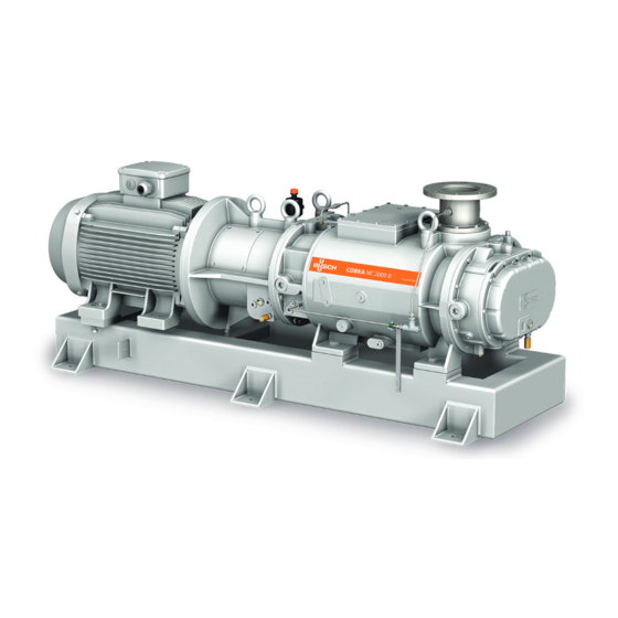
Summary of Contents for BUSCH COBRA NC 2000 B VR
- Page 1 Instruction Manual COBRA Dry Screw Vacuum Pumps NC 2000 B VR (Vapour Recovery) Ateliers Busch S.A. Zone industrielle, 2906 Chevenez VACUUM APP Switzerland 0870549537/A0004_en / Original instructions / Modifications reserved 2020.04.06...
-
Page 2: Table Of Contents
Table of Contents Table of Contents 1 Safety........................... 3 2 Product Description ..................... 4 2.1 Operating Principle....................5 2.2 Application ......................5 2.3 Start Controls ....................... 5 2.4 Standard Features....................5 2.4.1 Cooling......................5 2.4.2 Sealing Systems ..................5 2.5 Optional Accessories..................... 5 2.5.1 Resistance Thermometer................5 2.6 P&ID "Piping and Instrumentation Diagram"... -
Page 3: Safety
Safety Prior to handling the machine, this instruction manual should be read and understood. If anything needs to be clarified, please contact your Busch representative. Read this manual carefully before use and keep for future reference. This instruction manual remains valid as long as the customer does not change anything on the product. -
Page 4: Product Description
2 | Product Description Product Description TSA+/0101 TSA+/0102 Cooling liquid drain plug Cooling liquid inlet connection Cooling liquid outlet connection Eye bolt Earth connection (machine) Suction connection Injection point Magnetic plug Motor terminal box Nameplate Oil drain valve Oil fill plug Oil sight glass Discharge connection Resistance thermometer (option) -
Page 5: Operating Principle
Product Description | 2 2.1 Operating Principle The machine works on the one-stage, twin-screw pump principle. Two screw rotors are rotating inside the cylinder. The pumped medium is trapped between the cylinder and screw chambers, compressed, and transported to the gas out- let. -
Page 6: P&Id "Piping And Instrumentation Diagram
3 | Transport If a resistance thermometer is necessary to monitor the exhaust gas temperature, it may be installed in either the exhaust outlet flange of the pump or in a suitable prepared ex- haust spool piece at a distance of < 100 mm from the pump outlet. The machine must be stopped either when the cooling liquid temperature or when the exhaust gas temperature reaches the trip value, see Wiring Diagram Resistance Thermo- meter. -
Page 7: Storage
Storage | 4 • Make sure that the eyebolt(s) (EB) is/are in faultless condition, fully screwed in and tightened by hand. Machine weight: see the technical data or the nameplate (NP) l3 = ~1030 mm l1 = ~770 mm l2 = ~1020 mm •... -
Page 8: Installation
• Make sure that the cooling liquid complies with the requirements, see Installation and Commissioning Parameters [► 16]. If the machine is installed at an altitude greater than 1000 meters above sea level: • Contact your Busch representative, the motor should be derated or the ambient temperature limited. 5.2 Connecting Lines / Pipes •... -
Page 9: Suction Connection
– DN150 PN16, EN 1092-1 – ANSI 150, 6” (optional) If the machine is used as part of a vacuum system: • Busch recommends the installation of an isolation valve in order to prevent the machine from turning backwards. 5.2.2 Discharge Connection Connection size(s): –... -
Page 10: Cooling Liquid Connection
Earth connection of the machine (ECP) 5.4 Filling Oil NOTICE Use of an inappropriate oil. Risk of premature failure! Loss of efficiency! • Only use an oil type which has previously been approved and recommended by Busch. 10 / 28 0870549537_NC2000B_VR_A0004_IM_en... - Page 11 Installation | 5 For oil type and oil capacity see Technical Data [► 26] and Oil [► 26]. Oil filling at the motor side Check oil level Oil filling at the suction side Check oil level When the oil filling is achieved: •...
-
Page 12: Fitting The Coupling
Oil type see nameplate Change interval see instruction manual If there is no sticker (part no. 0565 568 959) on the machine: • Order it from your Busch representative. 5.5 Fitting the Coupling Coupling hub (motor side) Coupling hub (machine side) -
Page 13: Electrical Connection
• Provide an overload protection according to EN 60204-1 for the motor. • Make sure that the motor of the machine will not be affected by electric or electro- magnetic disturbance from the mains; if necessary seek advice from Busch. • Connect the protective earth conductor. -
Page 14: Wiring Diagram Three-Phase Motor (Pump Drive)
• Switch any two of the motor phase wires. 5.7 Electrical Connection of the Monitoring Devices NOTE In order to prevent potential nuisance alarms, Busch allows that the control system is configured with a time delay of 2 seconds. NOTE The accessories below are considered as standard. -
Page 15: Wiring Diagram Resistance Thermometer
Installation | 5 5.7.1 Wiring Diagram Resistance Thermometer Part no.: Wiring with transmitter: PT100: 0651 550 436 Transmitter: 0643 536 800 Supplier reference: PT100: Albert Balzer AG ref. TWBa-ADX50XG1/4X90DACB Transmitter: Endress+Hauser 1 = Brown ; 2 = Blue ref. TMT 187-B41FJA P&ID position: Wiring without transmitter: TSA+/0101 “cooling liquid temp.”... -
Page 16: Installation And Commissioning Parameters
Should the operating conditions of your machine fall outside of the recommended para- meters as outlined, please contact your local Busch agency for advice. Commissioning NOTICE The machine can be shipped without oil. -
Page 17: Start-Up
Commissioning | 6 CAUTION During operation the surface of the machine may reach temperatures of more than 70°C. Risk of burns! • Avoid contact with the machine during and directly after operation. CAUTION Noise of running machine. Risk of damage to hearing! If persons are present in the vicinity of a non noise insulated machine over extended periods: •... -
Page 18: Maintenance
Risk of injuries! Risk of premature failure and loss of efficiency! • Respect the maintenance intervals or ask your Busch representative for service. • Shut down the machine and lock against inadvertent start up. • Turn off the cooling liquid supply. -
Page 19: Maintenance Schedule
[► 19]. If the oil is contaminated or discol- oured, change the oil. • Check the machine for oil leaks - in case of leaks have the machine repaired (contact Busch). Yearly • Carry out a visual inspection and clean the machine from dust and dirt. -
Page 20: Oil Change
NOTICE Use of an inappropriate oil. Risk of premature failure! Loss of efficiency! • Only use an oil type which has previously been approved and recommended by Busch. Oil draining at the motor side Cleaning cloth Magnetic plug Drain pan... - Page 21 Maintenance | 7 Magnetic plug Oil draining at the suction side Cleaning cloth Magnetic plug Drain pan 0870549537_NC2000B_VR_A0004_IM_en 21 / 28...
- Page 22 7 | Maintenance For oil type and oil capacity see Technical Data [► 26] and Oil [► 26]. Oil filling at the motor side Check oil level Oil filling at the suction side Check oil level When the oil filling is achieved: •...
-
Page 23: Overhaul
• Decontaminate the machine as much as possible and state the contamination status in a ‘Declaration of Contamination’. Busch will only accept machines that come with a completely filled in and legally binding signed ‘Declaration of Contamination’. (Form downloadable from www.buschvacuum.com) NOTICE Improper assembly. -
Page 24: Dismantling And Disposal
• The exclusive use of Busch genuine spare parts and consumables is recommended for the correct functioning of the machine and to validate the warranty. There is no standard spare parts kits available for this product, if you require Busch gen- uine parts: •... - Page 25 • Seek advice from your local Busch representa- tive. Process deposits on the • Flush the machine. pumping components If an inlet screen or an inlet •...
-
Page 26: Technical Data
Oil capacity - motor side Oil capacity - suction side Weight approx. 2000 Please contact your Busch representative if the operating conditions fall outside of the recommended parameters as outlined. 13 Oil Shell Tellus S2 M Shell Tellus S2 V 68 TOTAL AZOLLA ZS... -
Page 27: Eu Declaration Of Conformity
This Declaration of Conformity and the CE-mark affixed to the nameplate are valid for the machine within the Busch scope of delivery. This Declaration of Conformity is issued under the sole responsibility of the manufacturer. When this machine is integrated into a superordinate machinery the manufacturer of the superordinate machinery (this can be the operating company, too) must conduct the conformity assessment process for the superordinate machine or plant, issue the Declaration of Conformity for it and affix the CE-mark. - Page 28 Chile Israel Portugal United Arab Emirates info@busch.cl service_sales@busch.co.il busch@busch.pt sales@busch.ae China Italy Romania United Kingdom info@busch-china.com info@busch.it office@buschromania.ro sales@busch.co.uk Colombia Japan Russia info@buschvacuum.co info@busch.co.jp info@busch.ru info@buschusa.com Czech Republic Korea Singapore info@buschvacuum.cz busch@busch.co.kr sales@busch.com.sg www.buschvacuum.com 0870549537/A0004_en / © Ateliers Busch S.A.
Need help?
Do you have a question about the COBRA NC 2000 B VR and is the answer not in the manual?
Questions and answers