Advertisement
Quick Links
Installation Manual for All Housings
CO
/ temperature sensor with built-in
2
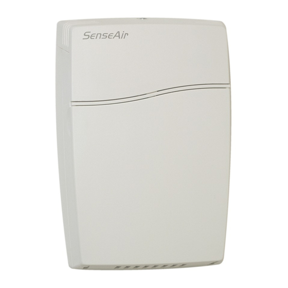
general purpose controller for wall mounting
5
1
4
3
Push the front part with the lid upwards
while keeping the wall plate steady
EM aSENSE-VAV (Modbus) all housings installation Oct'08
a a a a SENSE
SENSE™ VAV
SENSE
SENSE
1 top part
2 lid
3 front part
4 wall plate
5 screw
6 label with settings
2
inside the top part
6
VAV
VAV
VAV
Dismounting of the sensor
Pull the top part upwards
Fold the front part with the lid forwards
and loose it from the hooks (#1)
1
1 of 11
Advertisement

Related Manuals for SenseAir aSENSE VAV


Summary of Contents for SenseAir aSENSE VAV
- Page 1 Installation Manual for All Housings a a a a SENSE SENSE™ VAV SENSE SENSE / temperature sensor with built-in general purpose controller for wall mounting Dismounting of the sensor 1 top part 2 lid 3 front part 4 wall plate 5 screw 6 label with settings inside the top part...
- Page 2 Mounting of the sensor The wall plate is screwed onto the wall A Put the top tabs of the front part into the top holes of The screw heads should be max 4 mm the wall plate. B Press the lower edge of the case onto the wall plate to latch aSENSE™...
- Page 3 Dimensions and holes 31(1,22) 83(3,26) 120(4,72) Dimensions of sensor in mm and (inches) 30(1,18) 30(1,18) 4,2(0,16) 7,8(0,31) Dimensions of mounting plate in mm and (inches) 3 of 11 EM aSENSE-VAV (Modbus) all housings installation Oct'08...
- Page 4 aSENSE aSENSE aSENSE aSENSE™ VAV / temperature sensor with built-in general purpose controller for mounting in ventilation ducts 1 Sampling probe 6 O-ring 29,2x3,53 (Factory supplied mounted in box) 2 Sealing gasket 7 PCB (Factory supplied mounted in box) 3 Largest locking nob 8 Snap-in lid 4 2 washers BRB 5,3x10x1 9 PG9 cable entry bushing...
-
Page 5: Mounting Instruction
aSENSE aSENSE™ VAV aSENSE aSENSE Mounting of on to the duct. Hole with 25 mm diameter Temperature sensor with 110 mm cable mounted in the sampling probe Mounting Instruction Since there might be a substantial pressure difference in duct mounting applications, it is essential to avoid ambient air from suction into the duct-mounting box. - Page 6 aSENSE™ VAV Terminals and jumpers on standard The darker positions are default settings. Dimensions 85(3,35) 35(0,38) 10(0,39) 2,7(0,04) 40,3(1,59) 203,4(8,01) 40(1,57) Dimensions of sensor in mm and (inches) 55 (2,16) 66 (2,6) Dimensions of sampling probe in mm and (inches) 6 of 11 EM aSENSE-VAV (Modbus) all housings installation Oct'08...
- Page 7 a a a a SENSE SENSE SENSE™ VAV SENSE / temperature sensor with built-in general purpose controller mounted in industrial housing 1 Wall plate Snap-in lid 2 PCB (Factory supplied mounted in box) 6 Locking screw of the lid (not shown) 3 Temperature sensor PG9 cable entry bushing 4 Hole for wall plate hooks...
-
Page 8: Wall Mounting Instruction
9 Lid locking screw 10 Wall plate 11 Screw to hold the wall plate 12 Drill mark for cable entry bushing 13 Drill mark for cable entry bushing Dismounting the wall plate The sensor is delivered with the wall plate mounted. The wall plate has to be removed before the sensor is mounted onto the wall. - Page 9 aSENSE™ VAV Terminals and jumpers on standard The darker positions are default settings. 85 (3,35) 10(0,39) 38,5(1,5) 40 (1,57) Dimensions of sensor in mm and (inches) 63(2,48) 42(1,65) Ø5(0,20) Ø5(0,20) 41(1,61) Ø5(0,20) 82(3,23) Dimensions of wall plate in mm and (inches) 9 of 11 EM aSENSE-VAV (Modbus) all housings installation Oct'08...
-
Page 10: Electrical Connections
Electrical connections The power supply has to be connected to G+ and G0. G0 is considered as system ground. The aSENSE™ VAV same ground reference has to be used for the unit and for any connected device! Unless different transformers are used, special precautions need to be taken. PLEASE NOTE! The signal ground is not galvanically separated from aSENSE™... - Page 11 aSENSE™ VAV Note can deliver both a voltage or a current loop for OUT1/OUT2. For OUT4 a voltage output or an open collector output is selected with jumper OUT4. To change between voltage and current output mode the hardware jumpers are used. There is one jumper for OUT1 and one for OUT2, so that one output can be a voltage output and the other a current output.
Need help?
Do you have a question about the aSENSE VAV and is the answer not in the manual?
Questions and answers