Table of Contents
Advertisement
Quick Links
Function Description and Maintenance Instruction
aSENSE™ m III
CO
/ CO sensor with built-in general purpose
2
controller
General
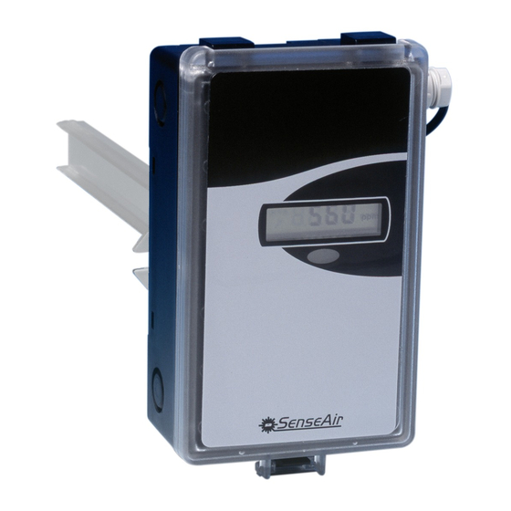
aSENSE™ m III
The IAQ-sensor product
is used to measure indoor air carbon dioxide and
carbon monoxide concentrations. It is a very flexible controller with programmable outputs
for both relay- and linear control of e.g. mixed air dampers, humidifier and fans. The
measured values are shown on the display.
The unit can alternatively be connected to common VAV (Variable Air Volume) controllers,
or Direct Digital Control (DDC). The linear output functions are pre-programmed. All
functions can be modified from a PC with the software UIP (version 4.3 or higher) and the
communication cable A232-05-07 CABLE.
aSENSE™ m III
Figure 1
.
for wall mounting and ventilation duct mounting
page 1 of 17
EM_aSENSE mIII_NC_function_Jan'08_GLL.doc
Advertisement
Table of Contents

Subscribe to Our Youtube Channel
Related Manuals for SenseAir aSENSE m III


Summary of Contents for SenseAir aSENSE m III
- Page 1 Function Description and Maintenance Instruction aSENSE™ m III / CO sensor with built-in general purpose controller General aSENSE™ m III The IAQ-sensor product is used to measure indoor air carbon dioxide and carbon monoxide concentrations. It is a very flexible controller with programmable outputs for both relay- and linear control of e.g.
-
Page 2: Functional Description
III is delivered pre-programmed (see description below). With the free software UIP4.3 (or later versions) and SenseAir’s standard communication cable for PC (art.no. A232 Cable) the user can adjust the product to his/hers application by, for example, changing the measurement ranges of the linear outputs, modify the set points of the alarm outputs, invert outputs and also reconfigure the functions and the logic that controls the outputs. - Page 3 Standard configuration: OUT1 is carbon monoxide output, OUT2 is carbon dioxide output and OUT3 is relay output. OUT4 is error status OR OUT3 is open. OUT1 = measuring signal for carbon monoxide concentration OUT2 = measuring signal for carbon dioxide concentration OUT3 = ON/OFF of demand of air quality.
-
Page 4: Output Configurations
Jumper top position provides 0Vdc or 0mA start point for OUT1, OUT2 Start point (0-20mA or 0-10V). selection jumper Jumper bottom position provides 2Vdc or 4mA start point for OUT1, OUT2 (4-20mA or 2-10V). Communi- Modbus communication protocol cation selection SenseAir communication protocol jumper page 4 of 17 EM_aSENSE mIII_NC_function_Jan'08_GLL.doc... - Page 5 Current Connection in position “Current” provides 0/4-20mA output range for OUT1. OUT1 Voltage Connection in position “Voltage” provides 0/2-10VDC output range for OUT1. Current Connection in position “Current” provides 0/4-20mA output range for OUT2. OUT2 Voltage Connection in position “Voltage” provides 0/2-10VDC output range for OUT2. Voltage Connection in position “Voltage”...
- Page 6 aSENSE™ m III Push Button Operation for This sensor has two push buttons, MENU and ESC. The YELLOW LED will acknowledge a successful push by a short flash. The push button MENU is available for selection of display value or maintenance commands, whereas ESC is available to escape back from a selected level.
-
Page 7: Display Modes
Display modes In DISPLAY MODE the DEFAULT operation is that the sensor alternates between carbon dioxide and carbon monoxide readings presentation. The push button MENU(+) is used to select the indicated value on the display to be the error code or the set points of temperature and CO After power up the display will always return to the Default display mode. - Page 8 Function Display Time Function description Line limit Access code to the service menu The default value of the code is 255 (=11111111, that is eight presses on MENU(+)). Press down ECxx MENU(+) and let it scroll until it stops. The last two digits of the code are shown.
- Page 9 EXAMPLE I: Setting of the MAX value of the analogue outputs The access code is time limited. If the time limit is exceeded the sensor returns to DEFAULT. ENTR =MENU(+) and ESC(-) are pushed simultaneously. At the start of the setting the sensor is in DEFAULT. Push MENU(+) once to reach the error code.
- Page 10 aSENSE™ m III Figure 9. Maintenance functions available on to set output limits. Only flow chart for setting High limits are shown, but Low limits are set in the very same way. The numbers in the flow chart refers to the points in example 1. Function blocks that are time limited are indicated by blue boarders.
- Page 11 EXAMPLE II: Setting of set points for carbon monoxide concentration and carbon dioxide concentration, the MAX and MIN values of the analogue outputs and calibration of the sensor The access code and the recalibration of the sensor are time limited. If the time limit is exceeded the sensor returns to DEFAULT.
- Page 12 Push ENTR(+-) to reach the output to be set. The display shows An and two digits e.g. An 01. Step to the requested output by pushing MENU(+). Push ENTR(+-) to reach the setting of the MIN value. The display shows Set L. Push ENTR(+-) to set the MIN value of the output.
-
Page 13: Functional Test
aSENSE™ m III FUNCTIONAL TEST of CO / CO Functional test The unit has three LED’s – green, yellow and red. These LED’s indicate the status of the controller. An internal delay function prevents the alarm functions of the relay and OUT4 output during 15 minutes after power up. -
Page 14: Self-Diagnostics
Gas inlet CO2 MENU MENU Gas inlet CO2 CAL CO CALb CO2 Figure 10. The PCB with the calibration jumper in default position. An enlarged part of the PCB with marked gas inlets and jumper positions for calibration is shown at right. PLEASE NOTE! The sensor accuracy is defined at continuous operation (at least 3 weeks after installation) Self diagnostics... -
Page 15: Maintenance
4.3 (or higher). This software can be free downloaded from www.senseair.com. A RS232-cable, article code A232-05-07 CABLE, is needed and can be ordered from SenseAir. The cable is to be connected to the UART port slide connector (Fig 10). For change of control parameters and re-calibration (CO and CO) this PC tool has to be used. - Page 16 MENU aSENSE™ m III Figure 10. The printed circuit board with the connection terminal area is enlarged. The terminal DI1 may be used for forced ventilation. If the sensor has a heater it is connected to G+ and G0. page 16 of 17 EM_aSENSE mIII_NC_function_Jan'08_GLL.doc...
-
Page 17: Warranty And Limitation Of Liability
1. SenseAir warrants that for a period of twentyfour (24) months following receipt by Buyer the Product supplied by SenseAir to Buyer will be, under normal use and care, free from defects in workmanship or material and to be in material conformity with SenseAir's specifications.
Need help?
Do you have a question about the aSENSE m III and is the answer not in the manual?
Questions and answers